
Passive RFID sensor tag

a sensor tag and passive technology, applied in the field of passive wireless sensors, can solve the problems of limited read-out distance, limited lifetime, wireless sensors, etc., and achieve the effect of large capacitance and larger amount of energy

Active Publication Date: 2016-03-03
METSO OUTOTEC (FINLAND) OY
View PDF3 Cites 16 Cited by
  • Summary
  • Abstract
  • Description
  • Claims
  • Application Information

AI Technical Summary

Benefits of technology

The invention includes a feature that allows a device called a transponder chip to store more energy from its surroundings for later use. This helps ensure that the chip can operate even when it receives no other signals or power sources.

Problems solved by technology

The technical problem addressed in this patent is how to manage and read multiple passive wireless sensors that differ in their sensor characteristics, including those made through research and development efforts. Previous solutions have focused on individual sensors instead of groups of similar sensors, leading to limitations in terms of flexibility and scalability. This patent seeks to address this issue by providing methods, routines, and arrangements for managing and reading multiple passive wireless sensors.

Method used


Image

  • Passive RFID sensor tag
  • Passive RFID sensor tag
  • Passive RFID sensor tag

Examples


Embodiment Construction

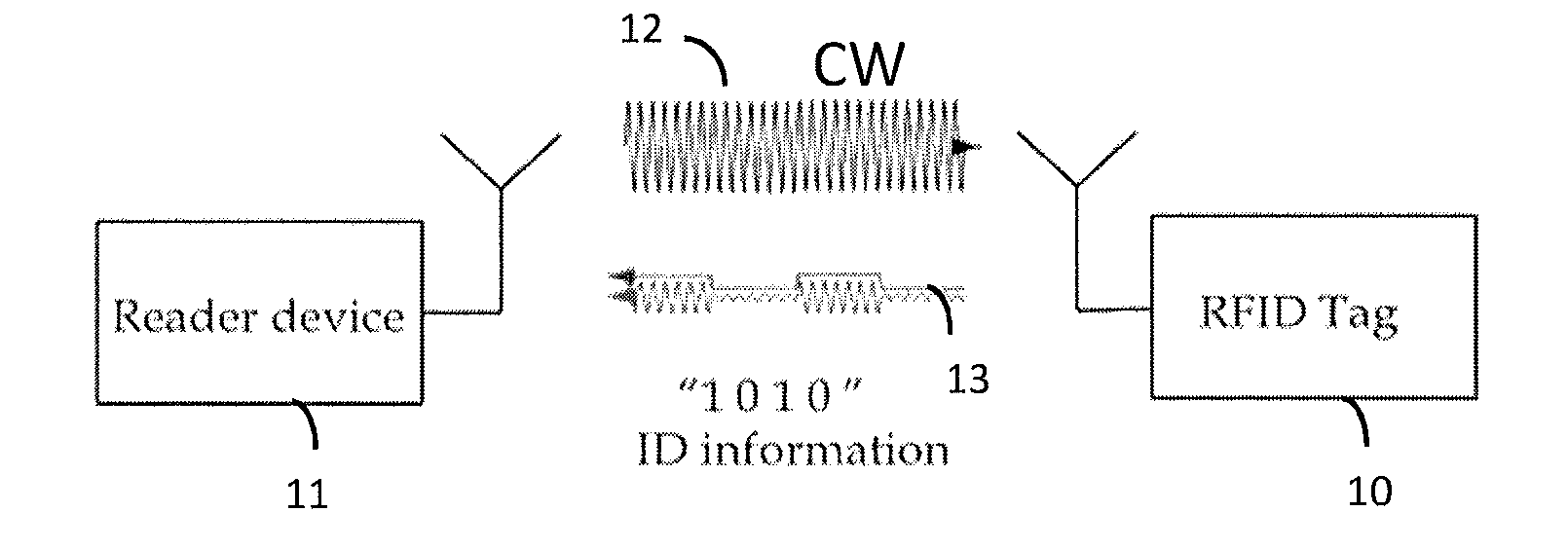
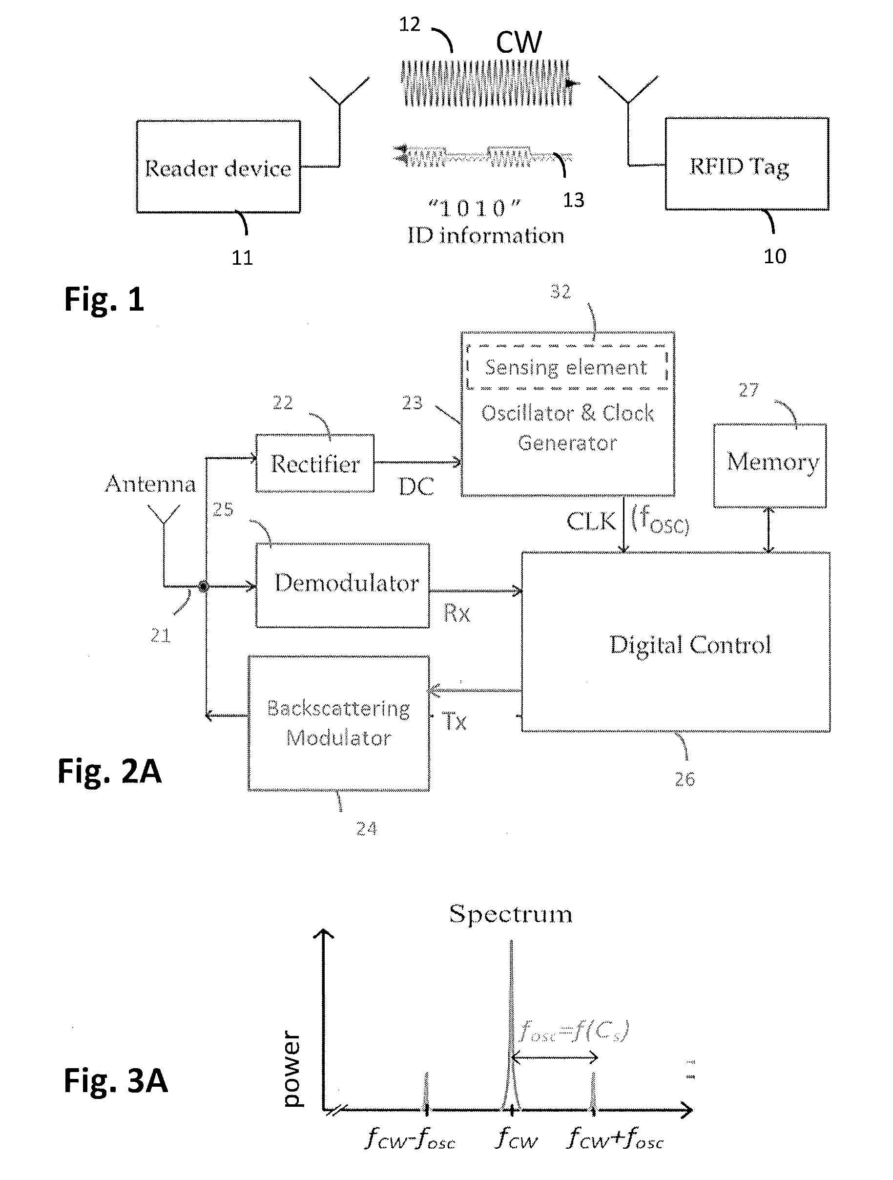
[0066]Referring to FIG. 1, an RFID system typically comprises two basic components: an RFID transponder or tag 10, which is located on the object to be identified or at a measurement point; an RFID interrogator or reader 11, which performs the interrogation of RFID tags. In a passive RFID system the RFID reader 11 supplies the tag 10 with essential power in order for it to perform modulation of the reader's interrogation signal. In the case of RFID sensor tags, in addition to just providing a power source and medium for the RFID tags 10 to operate and transmit data, an RFID reader 11 may perform data transmission, which is implemented, in most cases, as a modulation of the carrier signal, towards the tags 10.

[0067]FIG. 2A shows a functional block diagram illustrating a further example of radio frequency identity (RFID) tag architecture. In the illustrated example the RFID tag 10 may comprise an antenna 21 directly matched to the tag's front end impedance (matching circuit is not sho...


PUM


Abstract

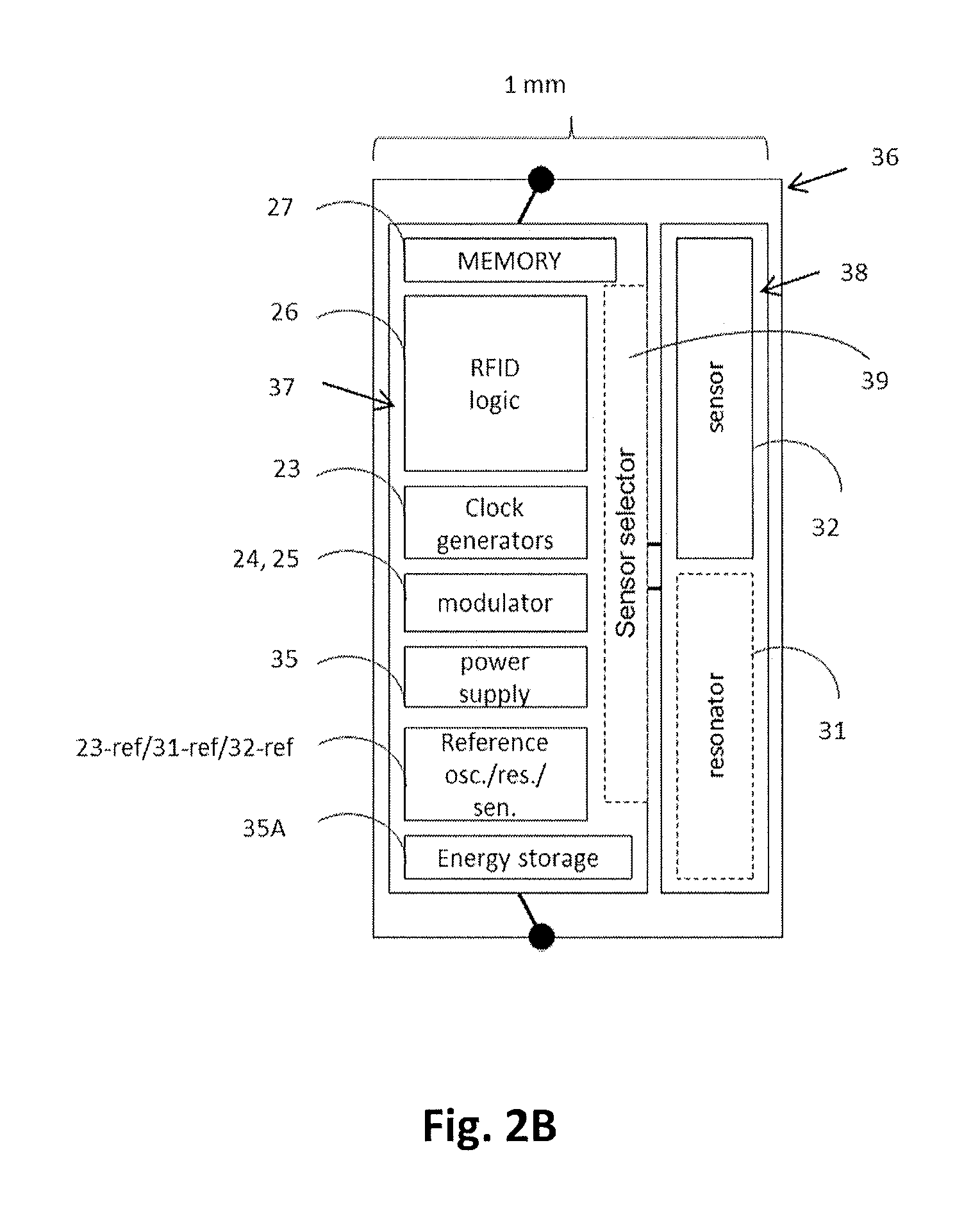
An integrated passive radio frequency identification transponder chip includes a backscatter modulator for communication with a backscattering principle, a tag oscillator generating a backscattering modulation frequency, and a reference load, preferably a reference resonator. Either the reference load or at least one pair of an internal or external resonator and an external sensor element can be selectively connected to load the tag oscillator. Each external sensing element is arranged to sense a predetermined variable. The tag oscillator is capable of generating any one of nominal backscattering modulation frequencies defined for a respective RFID system, when the reference load is connected to load the tag oscillator. The tag oscillator is arranged to generate a predetermined one of nominal backscattering modulation frequencies, when the at least one pair of the internal or external resonator and the external sensor element is connected to load the tag oscillator.

Description


Claims


Application Information

Patent Timeline
Owner METSO OUTOTEC (FINLAND) OY
Learn More