
A Traveling Camera Apparatus for Surfing

a technology for traveling cameras and surfers, applied in the direction of camera body details, instruments, stands/trestles, etc., can solve the problems of cameraman success, large amount of permits, and cost and time-consuming drawbacks, and achieve the effect of reducing drag and consuming more energy

Inactive Publication Date: 2008-12-25
ENJO JUSTIN
View PDF8 Cites 4 Cited by
  • Summary
  • Abstract
  • Description
  • Claims
  • Application Information

AI Technical Summary

Benefits of technology

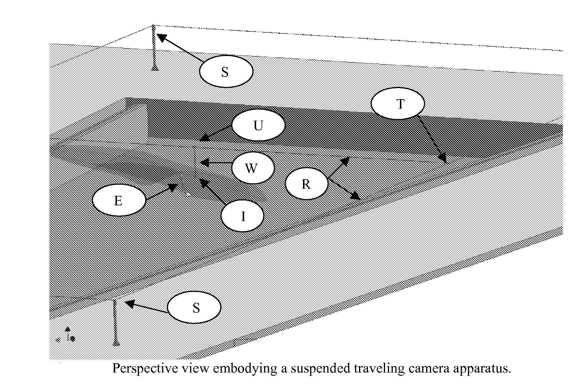
[0023]The camera shall be contained in a camera housing that is designed to protect and secure the camera in the environment of the wavepool. The camera will he housed by a casing designed to keep the camera dry and free from water and moisture, attach the camera to the traveling device, and that is hydro dynamically designed to travel underwater. The camera housing shall also protect the camera from underwater pressures up to the maximum depths of the wavepool and the maximum hydrostatic pressure experienced by the breaking wave, and have impact strength to withstand a surfer or subject possibly colliding or falling on the camera housing, and to also have a view window adequate not to constrict the lens of the camera.
[0027]The camera housing will be required to travel under water at speeds similar to a surfer traveling on a breaking wave. Surfers travel at speeds of 10 to 20 mph, frequently a little faster than the speed of propagation of the breaking wave. The hydrodynamics of the housing should allow the camera to travel underwater without causing obstruction to the view of the camera lens. A poorly streamlined housing will cause cavitations and bubbles will form that will restrict the camera's view of the subject. The housing will also have a viewing window that does not restrict the vision of the camera lens. A poorly streamlined housing will also generate a good deal of drag and require larger amounts of energy to drive the housing through the water.

Problems solved by technology

For example installing the apparatus on a reef would require a great deal of permits especially concerning environmental impacts, storm / disaster planning, and construction obstacles such as supplying power and machinery to remote aquatic environments.
The following examples show both the creative extents at which some cameramen have gone to capture rare and exciting surfing footage, as well as their costly and time consuming drawbacks.
The cameraman successfully followed the surfer's motion along the path of the breaking wave but at a cost.
The action of the PWC in front of the surfer causes disturbances to the water surface of the wave due to the wake of the PWC.
Unless the water surface is smooth, the operation of the PWC may be bumpy and cause difficulties in capturing steady video footage.
For the majority of the population the access to a helicopter for the means of filming surfing for recreation is uneconomical and costly.
In this case the cameraman has very limited mobility and can only pan the camera and adjust the zoom simultaneously to capture the surfer in passing.
It is impossible for the cameraman to swim fast enough underwater to film the entire duration of the surfer's ride.

Method used


Image

  • A Traveling Camera Apparatus for Surfing
  • A Traveling Camera Apparatus for Surfing
  • A Traveling Camera Apparatus for Surfing

Examples


Embodiment Construction

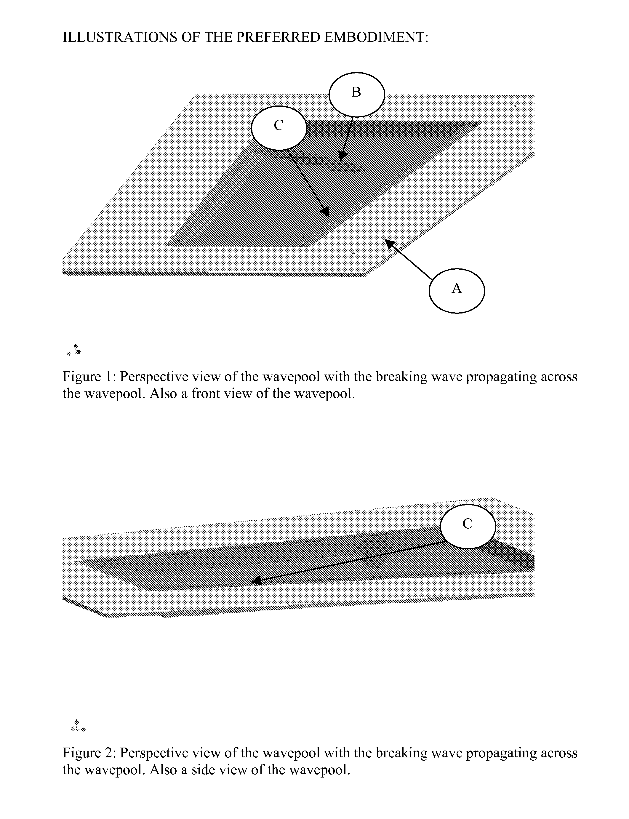
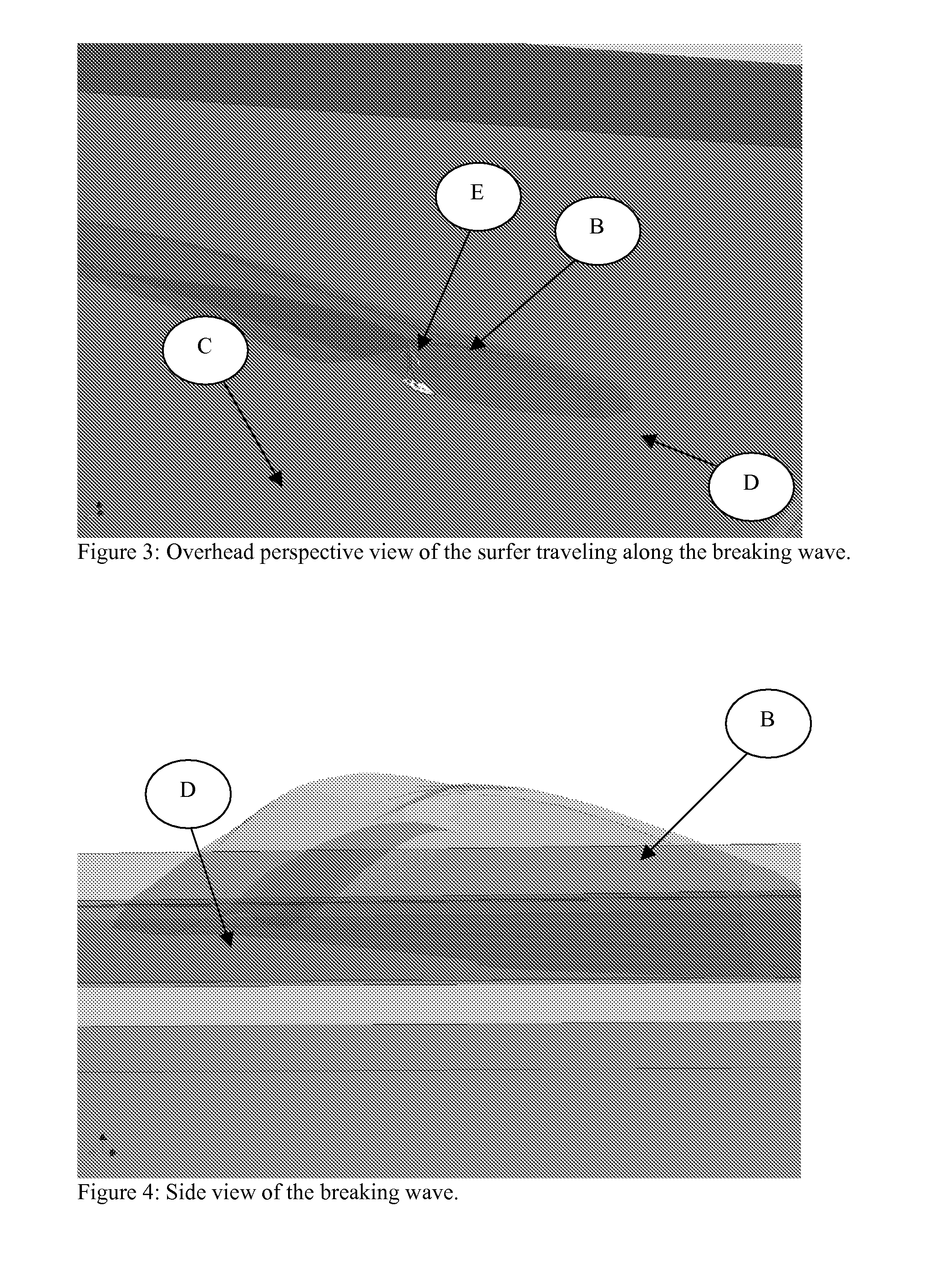
[0059]All figures show the surfer and the breaking wave traveling in the same direction, regardless of the orientation of the figure. Every object in every figure also remains static for the remainder of the report. Motion and paths of motion are mentioned and described in the patent but no sequential figures or “before and after” figures are given that show displacement of an object described to be in motion. Only the view or the orientation of the viewer changes with respect to the subject.

[0060]This presentation of the material is straight forward and in simplistic terms. By not changing the positions of the subject, breaking wave, camera, camera housing, suspension system, or mounting system, the presentation of the material becomes simpler.

[0061]FIGS. 1 to 26 are snapshots taken from a 3D rendering of apparatus. These figures are used to describe the embodiment of the invention and give the reader a detailed description of the inventions components and functionality.

[0062]FIG. ...


PUM


Abstract

The Traveling Camera Apparatus for Surfing is embodied to film and photograph a surfer in motion on a breaking wave. The Traveling Camera Apparatus for Surfing is intended to have a full range of motion with functionality in 6 degrees of freedom and with the ability to operate in and out of the water. The advent for such an apparatus is motivated by the advance of the surfing photography / videography industry. The economic feasibility of the invention is spawned by the advent of wavepools equipped with breaking wave making devices that impart to creating breaking waves for surfing in a controlled environment. In such a wavepool a surfer may travel an entire length of the wavepool as permitted by the propagation of the breaking wave. The Traveling Camera Apparatus for Surfing shall be designed to follow along side the subject and create a multitude of images not possible if the camera were stationary in the wavepool. Some popular and sought after vantage points in the surfing photography industry are obtained when the camera is located directly behind the surfer submerged in the breaking wave and directly adjacent to the surfer where the camera is actually submerged in the water body of the breaking wave. In order to film the motion the surfer over the entire duration of the breaking wave, these camera angles require that the camera actually travel a path across the pool similar to that of the surfer on the breaking wave.

Description

BACKGROUND OF THE INVENTION[0001]The invention begins by making two assumptions in that (1) there is a wavepool with breaking waves and (2) that these breaking waves can be ridden by a subject. Over 500 wavepools exist in the world today for the applications of hydrodynamic studies, wave theory study, the study of ships in a seaway, weather modeling, and recreation.[0002]A wavepool in this document relates to the subject of recreation in that the subjects ride the breaking waves for recreation. Notwithstanding the application of a Traveling Surfing Apparatus for Surfing is applicable in all types of wavepools for all types of filming applications. However, the primary sought after camera view of the Traveling Camera Apparatus for Surfing is obtained from viewing the subject when the camera is positioned inside the water body of the breaking wave.[0003]It should be noted that the application of the Traveling Surfing Apparatus for Surfing does in fact extend beyond the boundaries of a...

Claims


Application Information

Patent Timeline
Patent Type & Authority Applications(United States)
IPC IPC(8): G03B17/08
CPCG03B15/16G03B17/08F16M11/06F16M11/28F16M11/425F16M13/02
Inventor ENJO, JUSTIN
Owner ENJO JUSTIN
Learn More