High-damping absorbing coating

a technology of absorbent coating and high-damping, which is applied in the direction of spring/damper design characteristics, domestic objects, machine supports, etc., can solve the problems of limited effect of the first system and insufficient

Active Publication Date: 2006-11-02
EUROCOPTER
View PDF3 Cites 4 Cited by
  • Summary
  • Abstract
  • Description
  • Claims
  • Application Information

AI Technical Summary

Benefits of technology

[0009] An object of the present invention is to propose an absorbent covering that enables a considerable amount of damping to be applied to dynamic deformations of a structure.
[0011] Industrial manufacture of the dissipater mesh is made much easier when the mesh, and consequently also the nodes and the dissipater elements, is machined or molded as a single piece from a single block of deformable material, e.g. a plastics material.
[0014] In this way, the amount of energy dissipated in the absorbent layer is large, since the elastic material is deformed firstly by a lever arm effect caused by the nodes holding the dissipater elements away from the structure, and secondly by the dissipater elements sharing the stresses transmitted by the nodes throughout the elastic material while amplifying them by a geometrical effect. In order to optimize this amplification, at least one dissipater element is advantageously elliptical in shape, with each ellipse being connected to two nodes disposed at the points of intersection between the periphery of the ellipse and its major axis.
[0016] In addition, in the invention, the elastic material includes a plurality of recesses so as to enable it to work as efficiently as possible. These recesses then make it possible to reduce the weight of the absorbent covering significantly.

Problems solved by technology

Nevertheless, the effectiveness of that first system is limited since, as a result, the oscillation of the structure induces only small movements in the elastomer.
Nevertheless, for applications that require a large amount of vibratory energy to be dissipated, it is still not sufficient.

Method used


Image

  • High-damping absorbing coating
  • High-damping absorbing coating

Examples


first embodiment

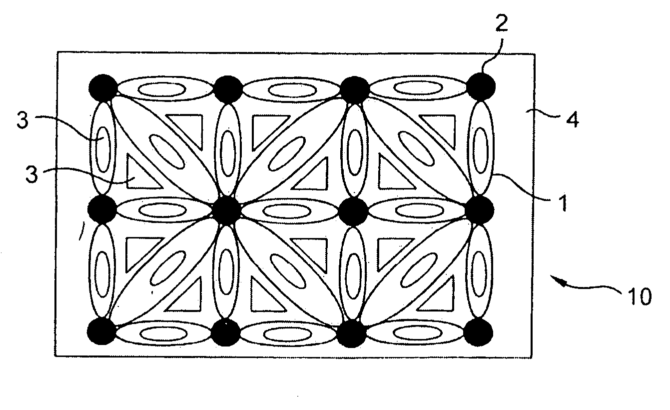
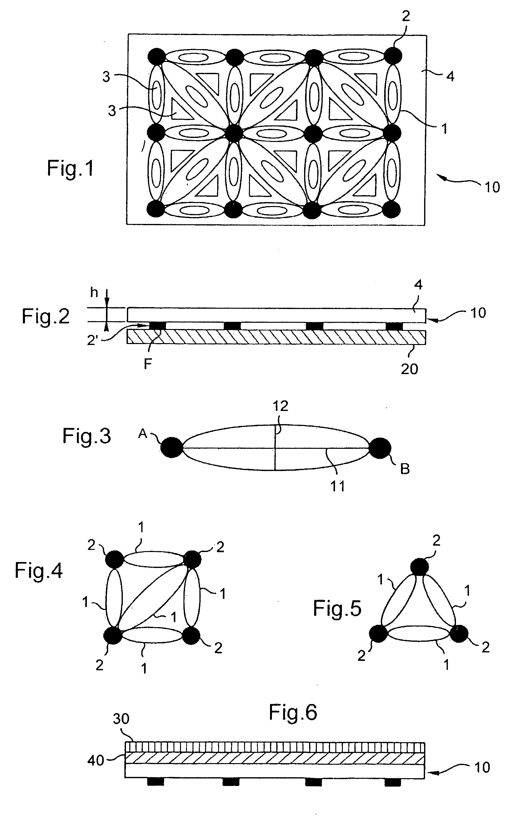
[0043]FIG. 4 shows a The dissipater mesh then comprises a repeated square pattern.

[0044] The square pattern comprises four nodes 2 and four dissipater elements 1 respectively constituting the corners and the sides of a square. In addition, a fifth dissipater element is disposed along one of the diagonals of the square.

second embodiment

[0045]FIG. 5 shows a In this embodiment, the repeated pattern of the dissipater mesh is triangular. Three nodes 2 and three dissipater elements 1 then represent respectively the corners and the sides of a triangle.

[0046] Depending on the level of stress applied to the structure, one or other embodiment is preferred.

[0047]FIG. 6 shows a variant of the invention.

[0048] In order to apply visco-stress to the elastic material 4, the absorbent covering includes a rigid backing plate 30.

[0049] In addition, in order to leave maximum latitude for displacement of the nodes 2 in the absorbent layer, an elastic backing plate 40 is arranged between the rigid backing plate 30 and the absorbent layer 10.


PUM

PropertyMeasurementUnit
damping poweraaaaaaaaaa
self-adhesiveaaaaaaaaaa
elasticaaaaaaaaaa

Abstract

The present invention relates to an absorbent covering having high damping power, the covering being secured to a structure (20) and being provided with an absorbent layer (10) of elastic material (4). Remarkably, said absorbent layer (10) comprises a dissipater mesh arranged in the elastic material (4) and constituted by a plurality of nodes (2) and of dissipater elements (1), which dissipater elements are advantageously elliptical in shape.

Description

FIELD OF THE INVENTION [0001] The present invention relates to an absorbent covering having high damping power, making it possible to reduce or even eliminate dynamic deformation of a structure as generated by vibration or by impacts, for example. [0002] More particularly, the absorbent covering of the invention is preferably intended for mounting on board a rotorcraft. In particular when installed on the walls of its cabin, the absorbent covering attenuates dynamic deformation of the walls so as to increase wall lifetime and reduce cabin noise. [0003] Naturally, the invention is not limited to this particular application and it can be used in any other application where there is a desire to reduce the dynamic deformation of a body. Given its design, it is optionally possible to envisage disposing the absorbent covering on the walls of a washing machine, for example, where electrical household appliances of this kind are subjected to high levels of vibration. BACKGROUND OF THE INVEN...

Claims


Application Information

Patent Timeline
Patent Type & Authority Applications(United States)
IPC IPC(8): B32B3/10B64C1/40F16F1/373F16F1/376F16F3/087F16F7/00F16F15/02F16F15/04F16F15/08
CPCB64C1/40F16F1/3737F16F1/376F16F15/04F16F2230/0047Y10T428/24347Y10T428/24322Y10T428/24298Y10T428/24479Y10T428/24339Y02T50/46Y02T50/40
Inventor MANFREDOTTI, THOMAS
Owner EUROCOPTER
Why Eureka
Try Eureka