Image forming apparatus

Inactive Publication Date: 2011-09-15
CANON KK
View PDF9 Cites 4 Cited by
  • Summary
  • Abstract
  • Description
  • Claims
  • Application Information

AI Technical Summary

Benefits of technology

[0056]Referring to FIG. 4B, in the non-development time, the non-development period C2 in the case that the environmental temperature is not lower than 30° C. (in the case of second embodiment, the case of the thick paper is equivalent) becomes about three times the non-development period C1 (see FIG. 4A) in the case that the environmental temperature is lower than 30° C. (in the case of second embodiment, the case of the plain paper is equivalent). The rotation speed of the development sleeve 5 during the non-development period C2, particularly during a low-speed rotation period F2. The rotation of the development sleeve 5 is started at a time t16 that is earlier than a time t17 the second development is started by a speed-up preparing period G2. This is because a time is necessary to reach a predetermined speed since the signal is transmitted to the motor. A motor characteristic is described below.
[0057]FIG. 4C is a sectional view illustrating a configuration of the development driving motor 40 that drives the development sleeve 5. The development driving motor 40 will be described with reference to FIG. 4C. Examples of the driving motor include a DC motor, a brushless motor, and a stepping motor. The power supply includes a direct-current (DC motor) power and an alternating-current (AC) power, and examples of the AC motor include a single-phase motor and a three-phase motor. A motor rotating method is classified into a synchronous fashion and an induction fashion. Recently, a permanent-magnet DC motor is frequently used. The development driving motor 40 has the following configuration. A voltage is applied to a lead from the power supply. A rotor 43 is rotated by a stator 44 to transmit a power to a shaft 41, thereby driving the development driving motor 40. The rotor 43 is fixed by a bearing 42. The stator 44 is fixed by a bracket 45. A principle in which the stator 44 (power supply) is converted into the rotor 43 (torque) can be classified into an electromagnetic motor in which a magnetic field and a current are used, an electrostatic motor in which an electric field phenomenon is used, and an ultrasonic motor. In such motors, frictional heat is generated when the rotor 43 is converted into a force. We can feel the motor is heated when touching the motor. Particularly, when the drive is started, that is, when the speed of the motor is enhanced, a large amount of energy is consumed. At this point, the energy except the energy used in the power (rotation energy) of the shaft 41 becomes thermal energy to consume the rotor 43 or the stator 44. For example, when the development driving motor 40 breaks down, because the electrostatic image cannot be visualized by the developer t, the image forming apparatus 13 is stopped to lead to a service call. The user feels uncomfortable because the user cannot use the image forming apparatus 13 for a longer time.
[0058]It is necessary to decrease

Problems solved by technology

Therefore, the developer bearing member uselessly rotates when the developer bearing member rotates while the electrostatic image absent region moves in a position opposite the developer bearing member.
The developer on the developer bearing member is degraded by the rotation of the developer bearing member, which results in degradation of image quality.
However, unfortunately, a down time or a consumed amount of toner that does not directly contribute to the

Method used


Image

  • Image forming apparatus
  • Image forming apparatus
  • Image forming apparatus

Examples


first embodiment

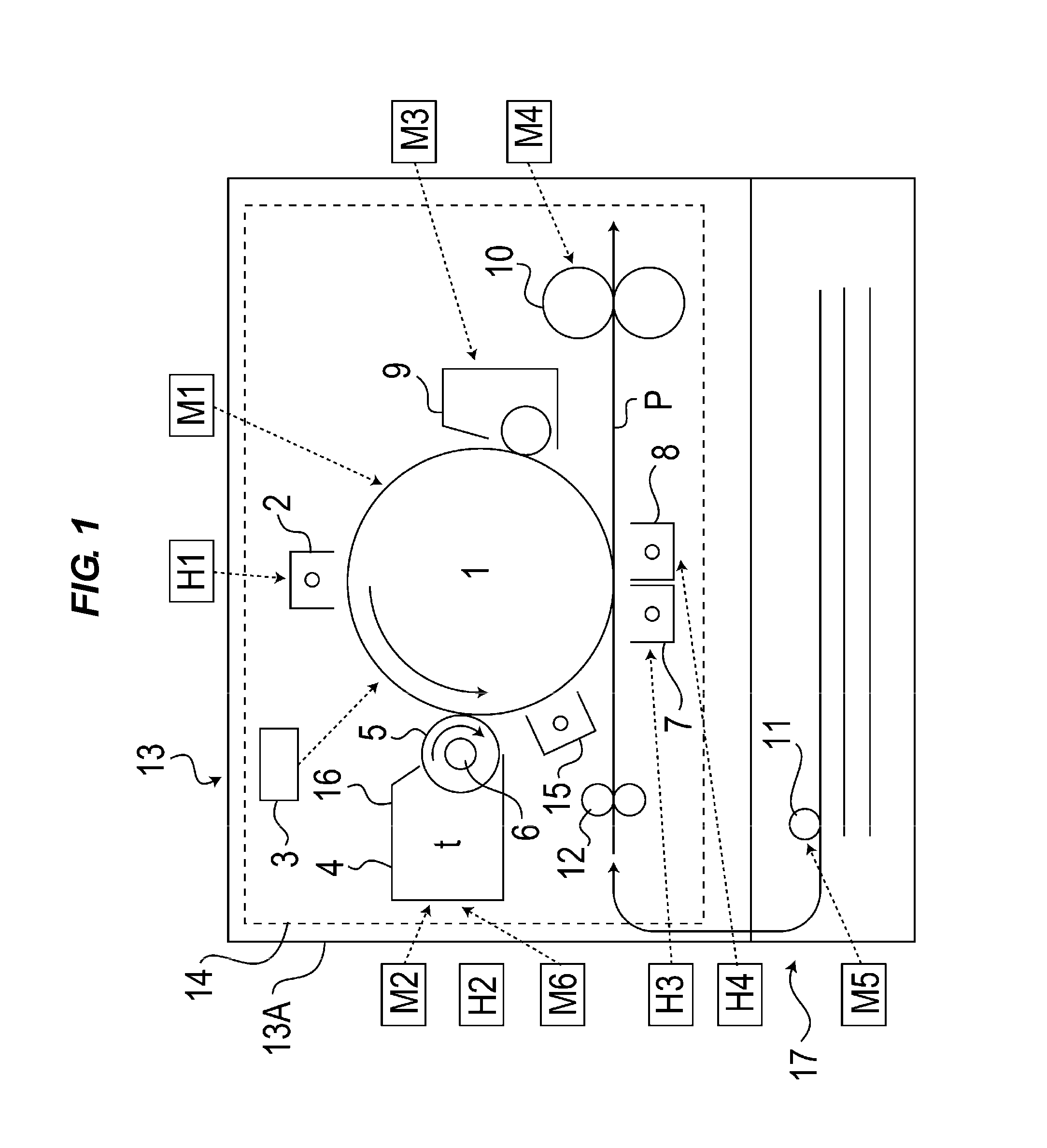
[0021]FIG. 1 is a sectional view illustrating a configuration of an image forming apparatus 13 according to a first embodiment of the present invention. The image forming apparatus 13 that is an “image input / output apparatus” has a duplex printing function in which an electrophotographic image forming process is used. As illustrated in FIG. 1, the image forming apparatus 13 includes an image forming apparatus main body (hereinafter, simply referred to as an “apparatus main body”) 13A, and an image forming portion 14 is provided in the apparatus main body 13A in order to form an image in a transfer material P. The image forming portion 14 includes a photosensitive drum 1 that is an “image bearing member”, and the photosensitive drum 1 rotates in an arrow direction of FIG. 1. The image forming portion 14 includes a charger 2 that is a “primary charger”, an exposure device 3, a development device 4, a post-charger 15, a transfer charger 7, a separating charger 8, and a cleaning device ...

second embodiment

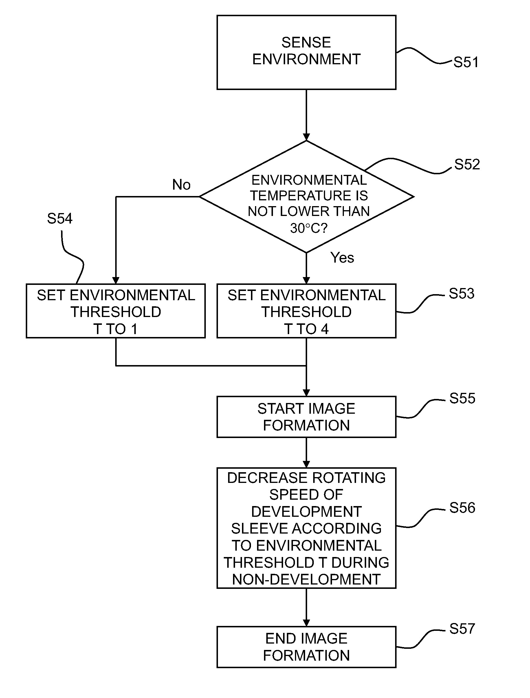
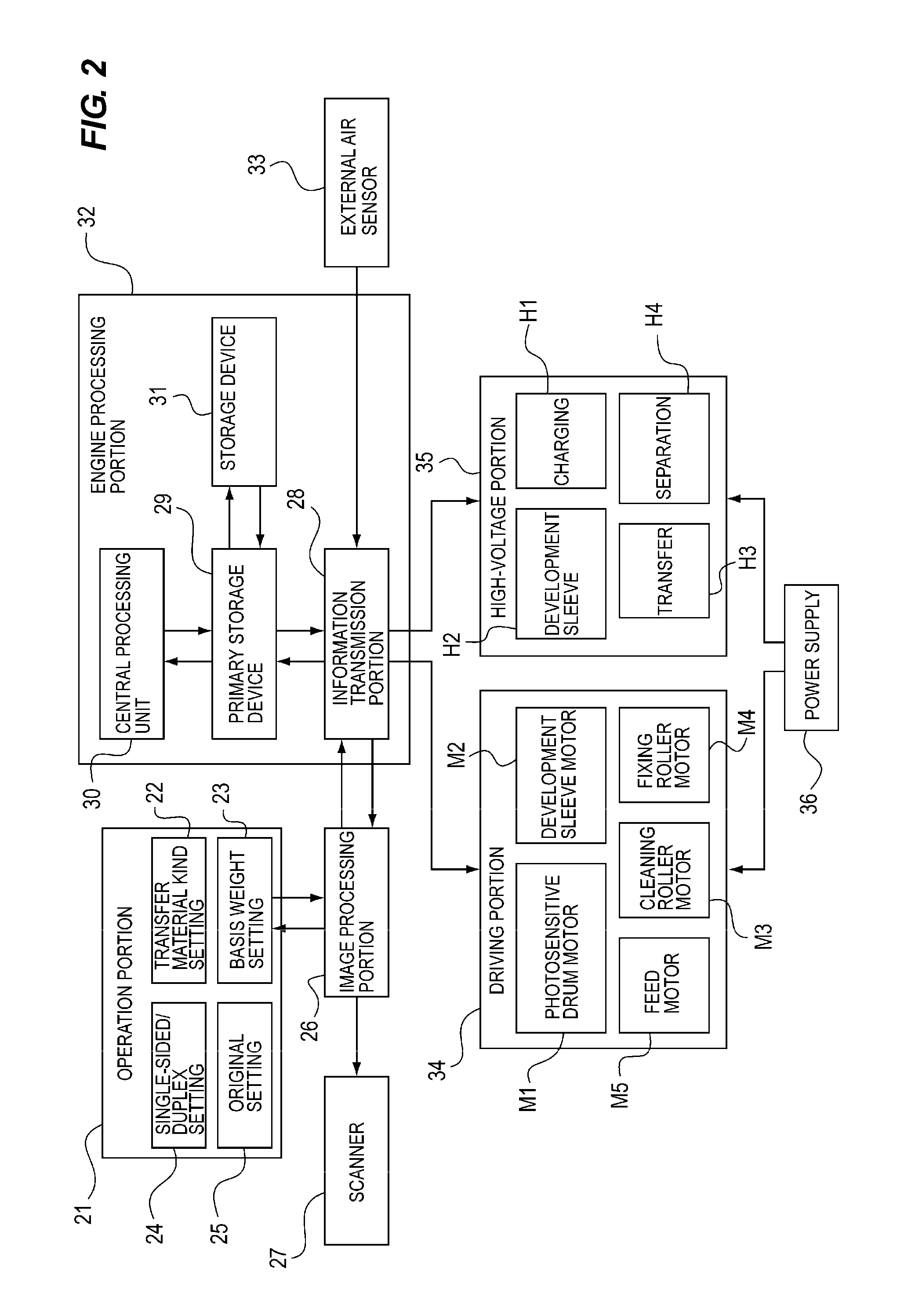
[0062]FIG. 5 is a flowchart illustrating a control process of an engine processing portion 32 according to a second embodiment of the invention. When the user selects the basis weight of the transfer material P, the engine processing portion 32 delays the rotation of the development sleeve 5 in the non-development time for the large basis weight of the transfer material P. The signal transmission and reception will be described with reference to a flowchart of FIG. 5 in addition to the sectional view of the image forming apparatus of FIG. 1 and the block diagram of the signal transmission of FIG. 2. The image forming operation is described below.

[0063]When the user inputs the basis weight of the transfer material P by the basis weight setting 23 (see FIG. 2) from the operation portion 21, the engine processing portion 32 starts the control (S1). The engine processing portion 32 determines whether the basis weight of the transfer material P is not lower than 210 g / cm2 (S2). When dete...

third embodiment

[0078]FIG. 6 is a timing chart illustrating a control process of an engine processing portion 32 of an image forming apparatus according to a third embodiment of the invention. A line N1 expresses both the development time and the non-development time. A line N2 and a line N3 express the driving signal of the development sleeve. In the image forming apparatus of the third embodiment, the same configuration and effect as those of the image forming apparatus 13 of the first and second embodiments are designated by the same numerals, and the description will not be repeated. The image forming apparatus of the third embodiment differs from the image forming apparatus of the first and second embodiments in that the number of times at which the rotation speed of the development sleeve 5 in the non-development time is increased.

[0079]In the third embodiment, the time the rotation speed of the development sleeve 5 in the non-development time is reduced is optimized when the basis weight of ...


PUM


Abstract

An image forming apparatus includes: an image bearing member; a development device; a speed varying unit that can vary a speed of a developer bearing member; a sensing portion that senses an environmental temperature around the development device; and a controller that can perform a mode in which, compared with a period which an image forming region of the image bearing member passes through the developing region, the rotation speed of the developer bearing member slows down a period which a non-image forming region of the image bearing member passes through the developing region, wherein based on sensing result of the sensing portion, the controller performs the mode when the environmental temperature is higher than a predetermined value, and the controller does not perform the mode when the environmental temperature is lower than the predetermined value.

Description

BACKGROUND OF THE INVENTION[0001]1. Field of the Invention[0002]The present invention relates to an image forming apparatus including an image bearing member and a development device that includes a developer bearing member, which can bear a developer, to visualize an electrostatic image on a surface of the image bearing member using toner borne by the developer bearing member.[0003]2. Description of the Related Art[0004]Recently, in the image forming apparatus such as a copying machine and a printer, it is necessary to rotate the image bearing member, the developer bearing member, and a fixing roller at a high speed in order to respond to high-speed printing that is the needs of a user. However, an amount of heat necessary to fix the toner depends on a kind of a transfer material. Therefore, sometimes image formation is performed while a gap between pieces of paper is widened, when the image formation is performed on the transfer material in which the large amount of heat is necess...

Claims


Application Information

Patent Timeline
IPC IPC(8): G03G15/00G03G15/08
CPCG03G15/0818G03G2215/00772G03G15/50
Inventor KABASHIMA, TORU
Owner CANON KK
Why Eureka
Try Eureka