Emergency flashing light system

a flashing light and emergency technology, applied in the direction of visible signalling system, signalling system, instruments, etc., can solve the problems of delay in providing assistance, and difficult to locate a particular residence at night and in rural areas

Inactive Publication Date: 2016-03-03
FIORE PAUL
View PDF5 Cites 8 Cited by
  • Summary
  • Abstract
  • Description
  • Claims
  • Application Information

AI Technical Summary

Benefits of technology

The present invention is a light flashing system that can be added to an existing light switch to turn it into a manual or remote-controlled light switch. The system includes a rigid housing that is secured over the switch and contains a switching system that operates the switch repeatedly. The housing also has a communication system that allows control and operation from remote locations. The system can be installed without interacting with the electrical components of the switch and can be used with different types of lighting switches. The main benefit is that the system can provide more flexibility and control over the lighting device.

Problems solved by technology

In most cases it remains difficult to locate a particular residence because of hard to read or missing house numbers.
Moreover, even with advances in GPS technology, it remains difficult to locate a residence at night and in rural areas.
While many of these systems alert authorities of a person's need for assistance, and even provide information of the person's location, such systems do not include any feature for alerting first responders to the physical residence, thus usually creating delay in providing assistance.
Thus, these services often fail at providing assistance to those responding to the physical residence where assistance is sought.
Notwithstanding, while emergency services may be able to contact first responders, nothing is done to potentially alert neighbors that someone may be in trouble.
While it is appreciated that emergency services may be able to respond fairly quickly, delays may occur, or an individual needing assistance may need immediate intervention which first responders may be slow to provide.
For example, pizza delivery services often encounter similar issues in finding a person's home in the evening due to the inability of GPS to exactly resolve an address and poorly lit house numbers.
Several flashing light switch controllers are also known in the art, such as in U.S. Pat. No. 5,406,129, but these are limited in having to be activated manually.
Thus, these systems do not allow for the surface mounting of a flasher over an existing switch, rather the flashers known in the art require the use of a skilled electrician to install.
No device exists which solves any or all of these unmet needs.

Method used


Image

  • Emergency flashing light system
  • Emergency flashing light system
  • Emergency flashing light system

Examples


Embodiment Construction

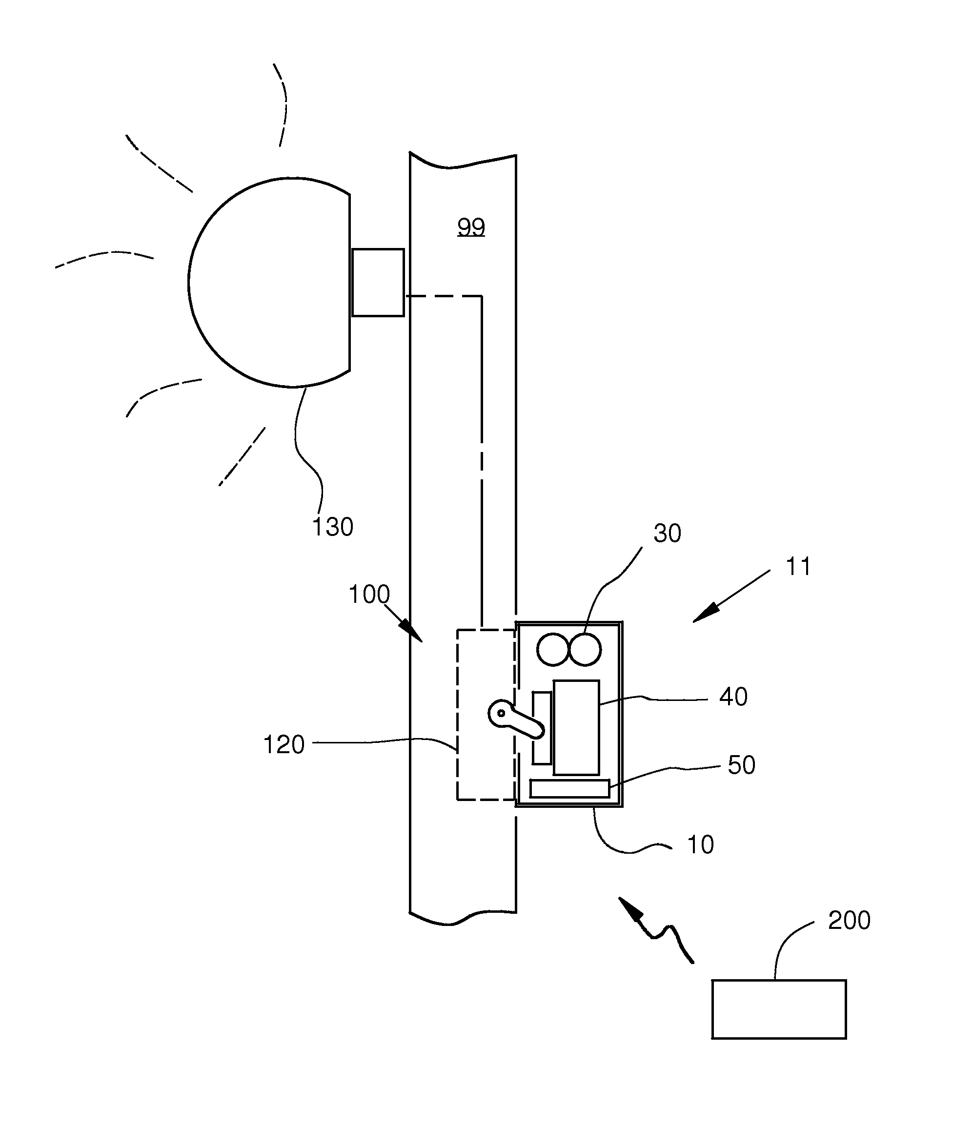
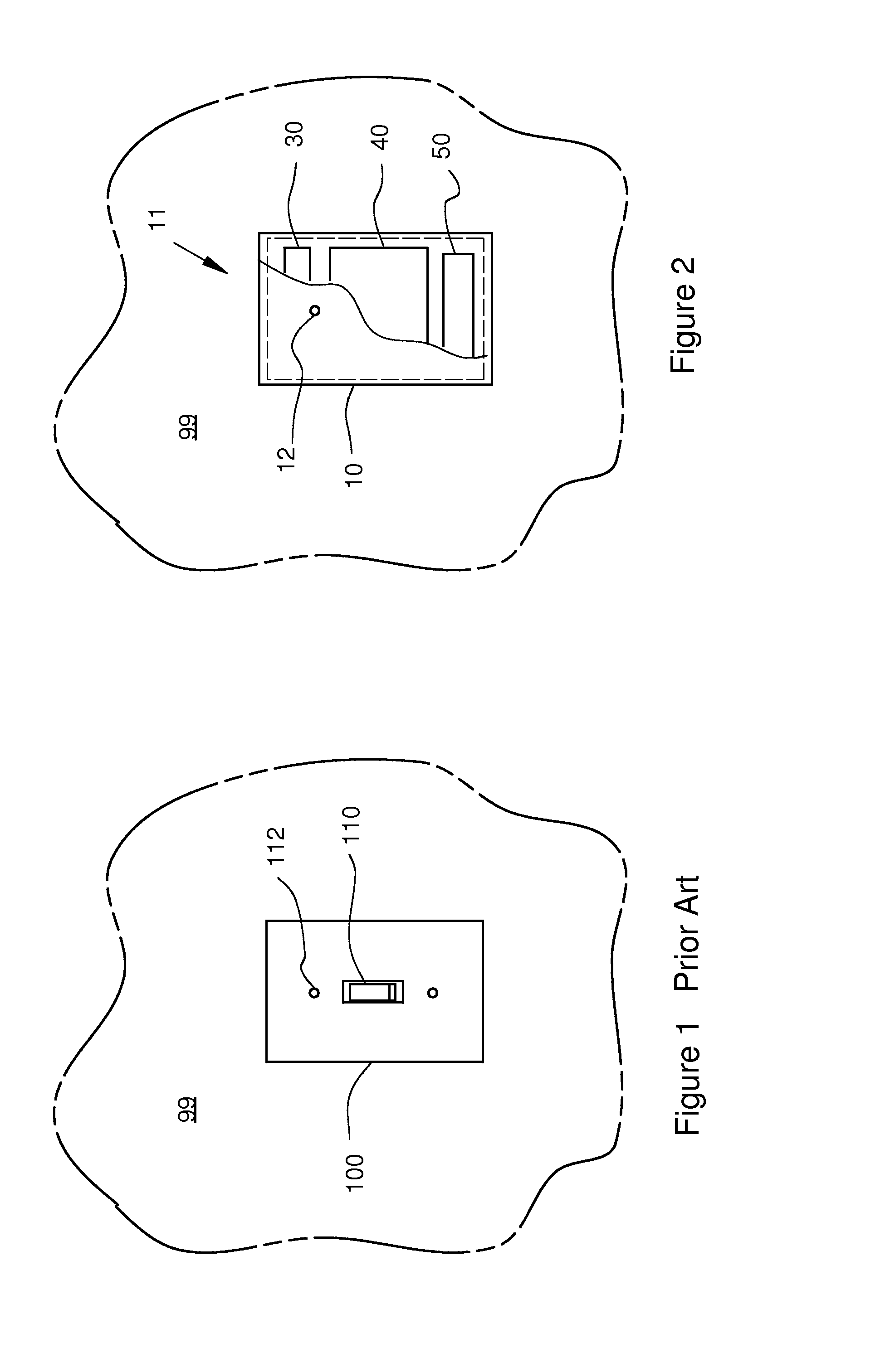
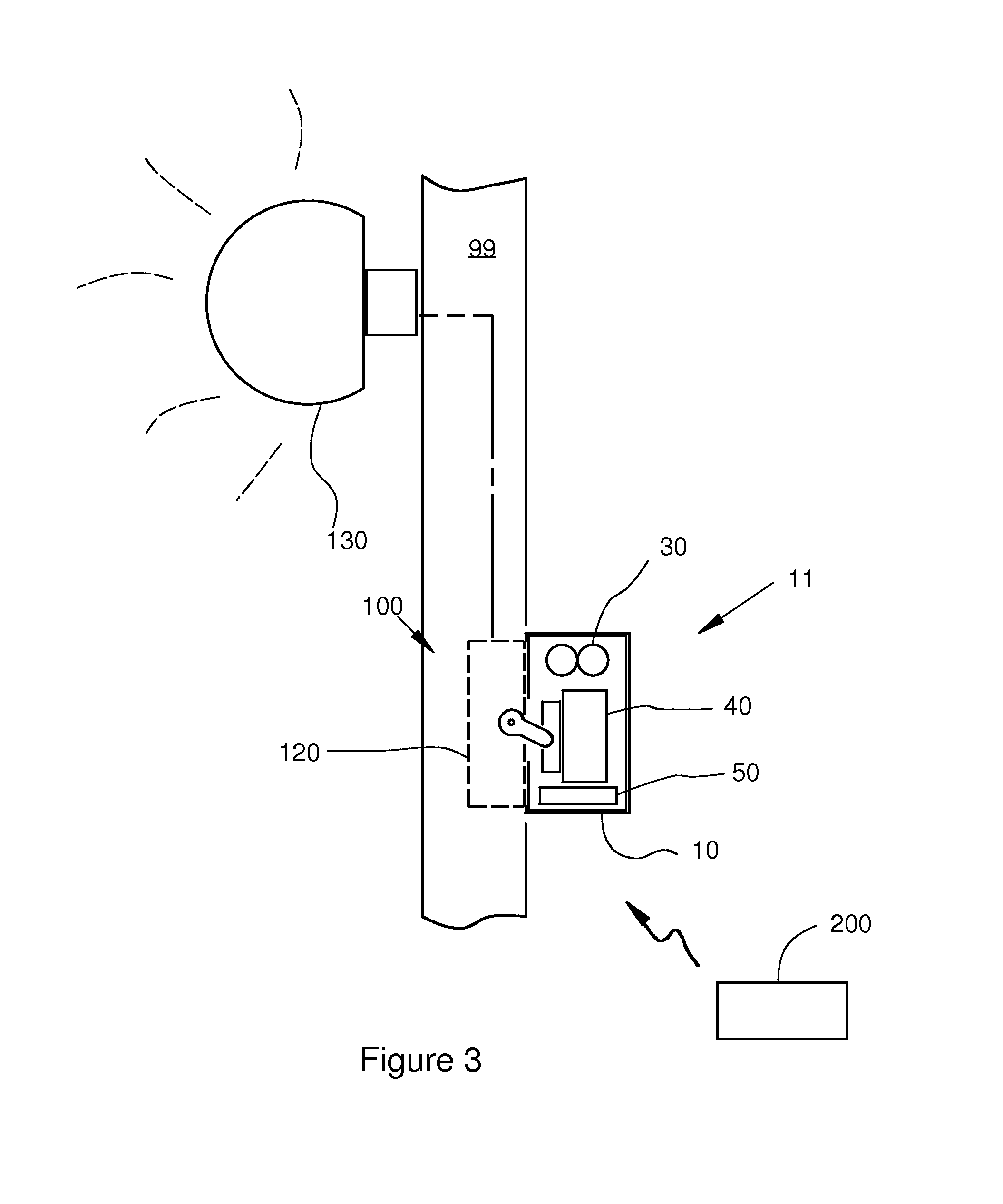
[0016]The present invention is directed to a light flashing system that fits over an existing light switch in order to convert a conventional light switch into a manually operated or remotely controlled light switch enabling flashing operation of a connected lighting device.

[0017]The following detailed description is merely exemplary in nature and is in no way intended to limit the scope of the invention, its application, or uses, which may vary. The invention is described with relation to the non-limiting definitions and terminology included herein. These definitions and terminology are not designed to function as a limitation on the scope or practice of the invention, but are presented for illustrative and descriptive purposes only.

[0018]It is to be understood that in instances where a range of values are provided that the range is intended to encompass not only the end point values of the range but also intermediate values of the range as explicitly being included within the rang...


PUM


Abstract

A light flashing system is provided that fits over an existing conventional light switch in order to convert the conventional light switch into a remotely controlled light switch providing repeated, flashing, operation of an associated light. Manual operation is also a possible. The system provides emergency flashing operation of a residence external light through remote initiation of a user.

Description

FIELD OF INVENTION[0001]The present invention is in the field of electrical devices for controlling light switches. More particularly, the invention pertains to electrical devices for attaching to existing light switches to allow the light switch to be remotely actuated and function as a flashing light for alerting individuals.BACKGROUND[0002]When first responders such as emergency medical personnel, police, or firefighters are responding to an emergency distress call, it is important for them to locate the residence where the distress call came from quickly. In most cases it remains difficult to locate a particular residence because of hard to read or missing house numbers. Moreover, even with advances in GPS technology, it remains difficult to locate a residence at night and in rural areas. Thus there exists a need for a way to assist emergency responders to pinpoint a house which has asked for emergency assistance.[0003]Several human monitoring or geriatric monitoring services, s...

Claims


Application Information

Patent Timeline
Patent Type & Authority Applications(United States)
IPC IPC(8): G08B5/38
CPCG08B5/38
Inventor FIORE, PAUL
Owner FIORE PAUL
Why Eureka
Try Eureka