[0004]An object of the present invention is to provide an optical switch that overcomes the limitations of the above noted prior art. Another object of the inventions is to provide an optical switching unit which is relatively low in cost, has high speed and is reliable in operation. Briefly in accordance of the invention, an improved optical
light transmission switch employs a microelectromechanical (hereinafter MEM) movable mirror
assembly with associated
electromagnet coils mounted in a
package and preferably including control LED's with both drive and LED signals being supplied through a wiring harness. The following described preferred embodiments relate to a hermetic
package using
inorganic materials in order to provide extended life, however, units can be made which include organic materials for other shorter life applications.
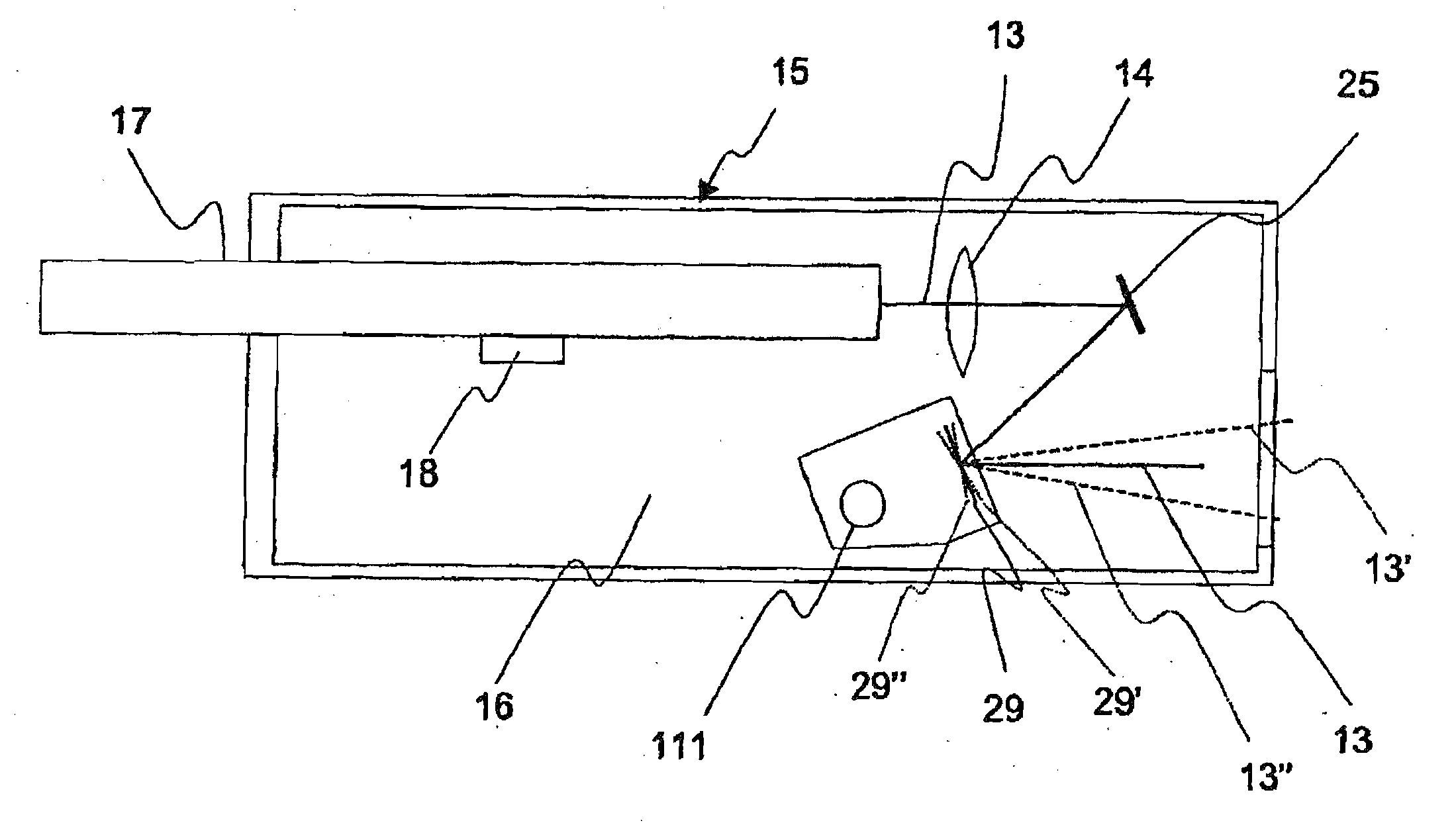
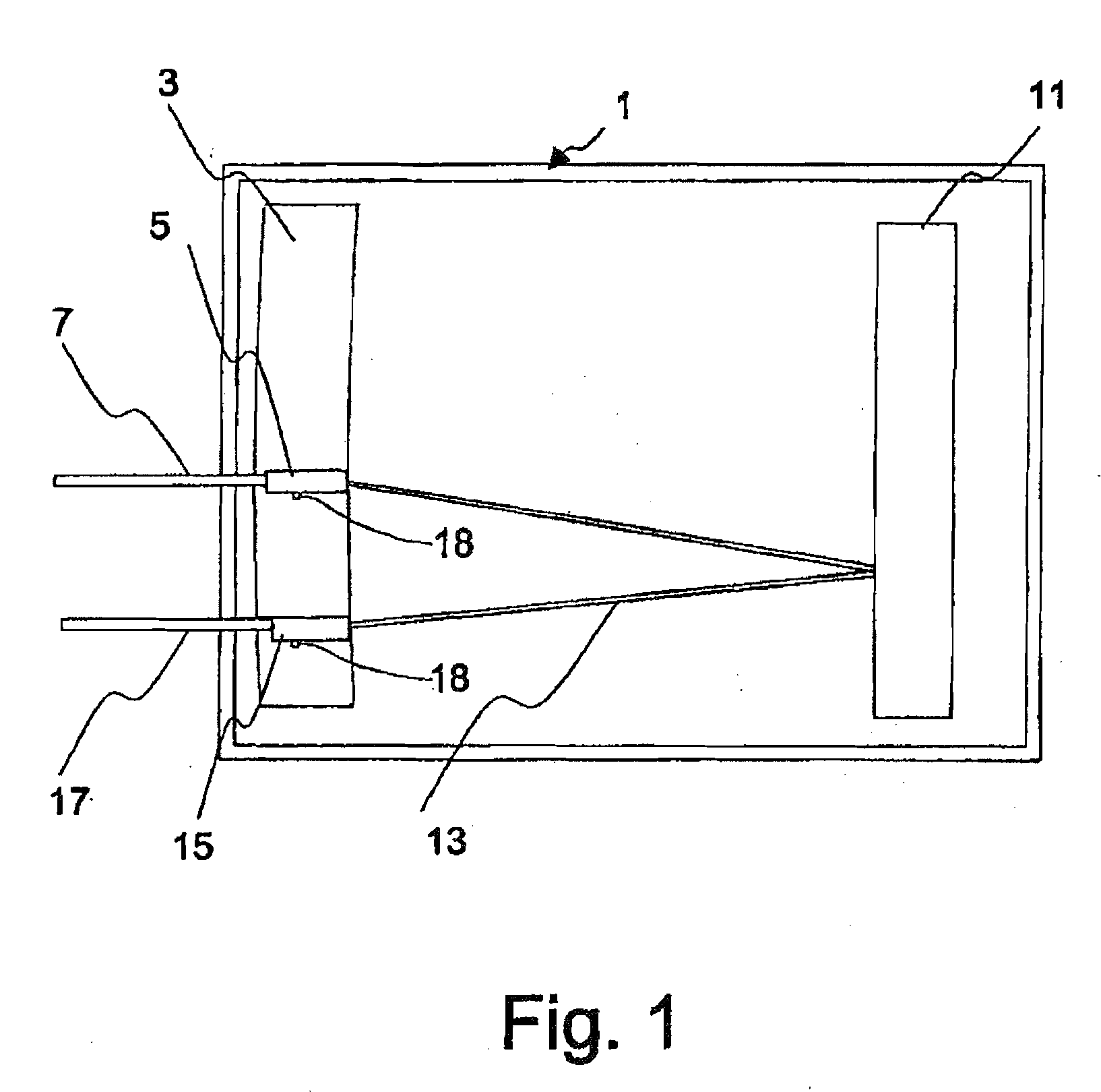
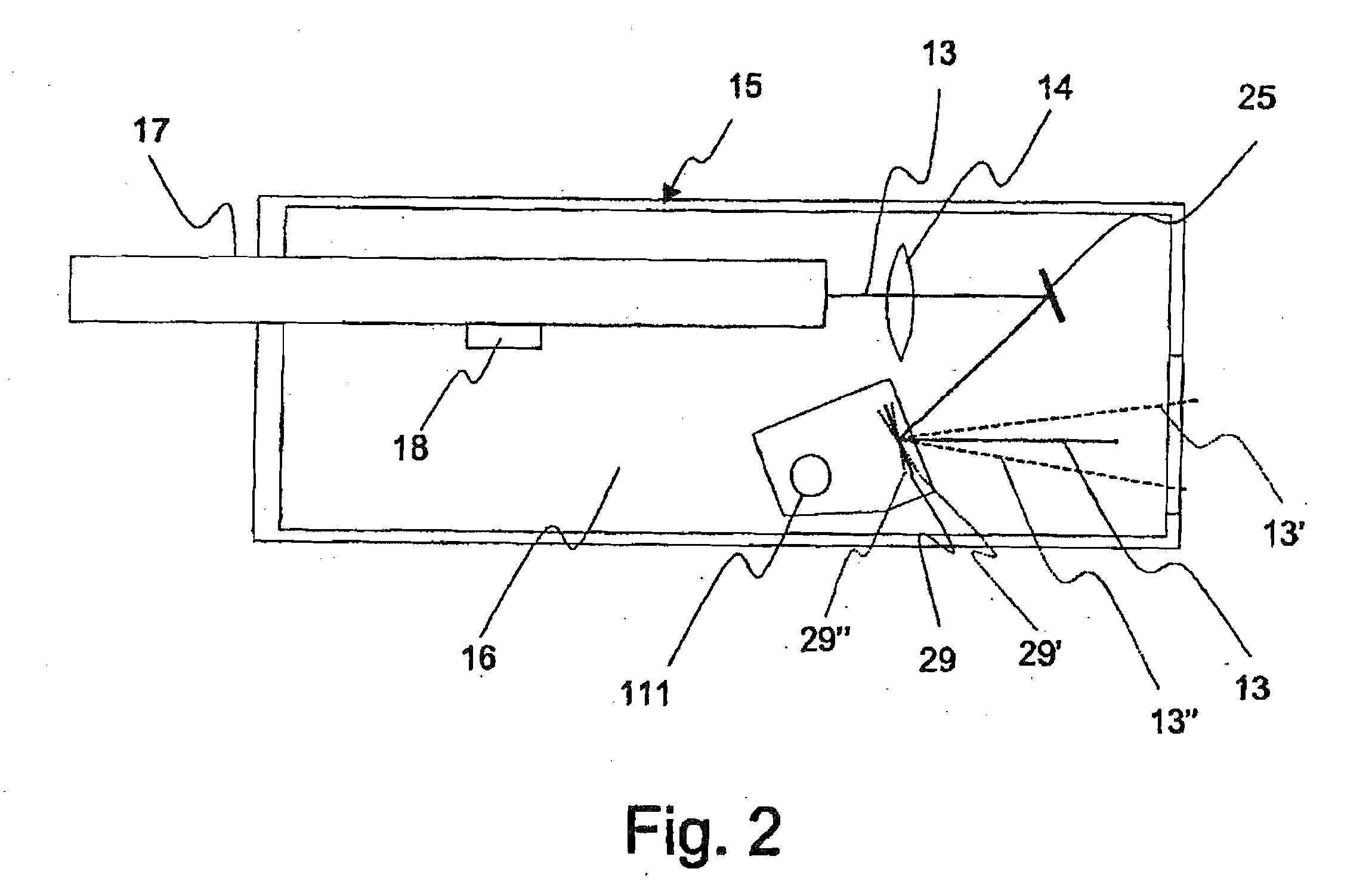
[0005]The package comprises an LED
lead frame of suitable material such as
ceramic, which mounts LED's used by the
control system to aim the movable mirror as well as circuitry to electrically connect the LED's to their package terminations. As will be discussed below, the LED's provide signals for controlling the position of the movable mirror so that any two mirrors in an array can be positioned to reflect a
light beam precisely at each other so that the
light beam is focused entirely on the reflective surface of the mirrors and in that way no energy of the beam is lost in the reflection process of the switched connection. The LED's are die and wire bonded to the
lead frame using conventional techniques. The LED's are located so that lines drawn through diagnonal pairs would pass through a selected location on the
lead frame which is referenced the movable mirror. A mirror assembly, described below, is attached to the lead frame so that the center of the mirror portion coincides with the selected location on the lead frame in order to accurately locate the mirror relative to one another for proper control of
mirror movement. The mirror assembly and lead frame are mounted in a header of suitable material, such as
ceramic which, along with driving means and a wiring harness, are in turn mounted on a bracket. The package is received in a housing in which an
optical fiber is received and in which another mirror is disposed in alignment with the fiber for reflecting an optical
signal from the fiber to the movable mirror.
[0008]According to a feature of the invention, an additional
magnet is provided at each
magnet location, with the poles in opposing relationship to each other and disposed on the opposite face of mirror assembly to balance the weight of the magnets relative to the hinge centerlines of the mirror assembly, eliminating undesirable oscillations under external shock or other conditions.
[0010]According to another feature of the invention, motion stops, disposed in a plane described by the two axes of rotation, are added to the mirror assembly at each hinge location to limit motion and thereby prevent failure of the hinge. Tabs are preferably formed in the plane described by the two axes of rotation, extending from the mirror portion to the gimbals portion and from the gimbals portion to the frame portion, to prevent rotation during initial manufacture. Sometime prior to final assembly,
laser or other suitable
cutting means severs the tabs, preferably perpendicular to each respective axis of the hinges, to allow
free rotation.
[0011]In order to obtain extended operation without degradation, the mirror assembly is preferably hermetically assembled into a cavity in the package to lock out
moisture and allow the provision of a benign
atmosphere for micromirror operation. The cavity can be filled with selected gases to provide improved
heat transfer and, if desired, exclude
oxygen or other gases that would adversely affect the micromirror over time. The hermetic package comprises the header in which the cavity is formed and which includes sealed pins for electrical LED connection pins. A
peripheral seat surface on the header extending around the cavity is coated with
indium or suitable non-organic seal materials, for later attachment of a window over the cavity. The use of
indium allows the seal to be made at
room temperature to avoid seal
temperature induced stresses and window distortions.
Indium or other non-organic attach materials are used exclusively to assembly all items within the
body cavity of the hermetic package, avoiding any unwanted long term organic out gassing or other similar problems.
[0014]An air coil drive assembly is used and preferably employs a
push and pull arrangement for driving the mirror magnets to rotate the mirror portion to the desired orientation in its two axes. Four air coil assemblies, comprising
copper wire coiled on a
bobbin, are attached to a mounting bracket,
trapping a flex circuit harness and are aligned with the mirror assembly. The air coil leads are soldered to the flex circuit harness to allow
system electrical control of the air coils and their
push pull arrangement to drive the mirror assembly. The air coil bobbins are made of aluminum or other
eddy current generating material, and sufficient amounts of aluminum are provided at the top and bottom of the bobbins to allow
eddy current dampening of the movable portions of the mirror assembly, to prevent unwanted oscillations. In order to prevent overheating and loss of mirror
position control, the air coil bobbins are made of
high heat transfer material, such as aluminum, and the bobbins are massive relative to the air coils. The mounting bracket is massive relative to the bobbins and is also made of a
high heat transfer material, such as aluminum. The bracket is in intimate contact with the optical
unit housing, which in turn is in intimate contact with the ultimate heat sinking of the customers
system.

