Eureka AIR delivers breakthrough ideas for toughest innovation challenges, trusted by R&D personnel around the world.

Conductive path

Active Publication Date: 2016-03-03
SUMITOMO WIRING SYST LTD
View PDF6 Cites 0 Cited by
  • Summary
  • Abstract
  • Description
  • Claims
  • Application Information

AI Technical Summary

Benefits of technology

The patent text discusses the problem of reducing the diameter dimension of the pipe as much as possible in the conductive path routed under the bottom of a vehicle. To address this problem, the text proposes using single-core electrical lines instead of stranded electrical lines, which can have a larger diameter dimension. Connecting the stranded electrical lines to the single-core electrical lines can be easier, and the width dimension of the conductive path can be prevented from increasing. The technical effect of this invention is to provide a conductive path that allows easy connection of the stranded electrical lines to the single-core electrical lines, without increasing the width dimension of the conductive path.

Problems solved by technology

This because if the junction portion between the single-core electrical line and the stranded electrical line, which is prone to having a larger width dimension, is connected first, the junction portion needs to be inserted into the pipe, and it becomes more difficult to reduce the diameter dimension of the pipe.
However, it is thought that the task of connecting stranded electrical lines to the end portions of multiple single-core electrical lines drawn out from the pipe is not easy, and there has been a desire for a solution.

Method used


Image

  • Conductive path
  • Conductive path
  • Conductive path

Examples


embodiments

[0020]The following is a detailed description of an exemplary embodiment with reference to FIGS. 1 to 4.

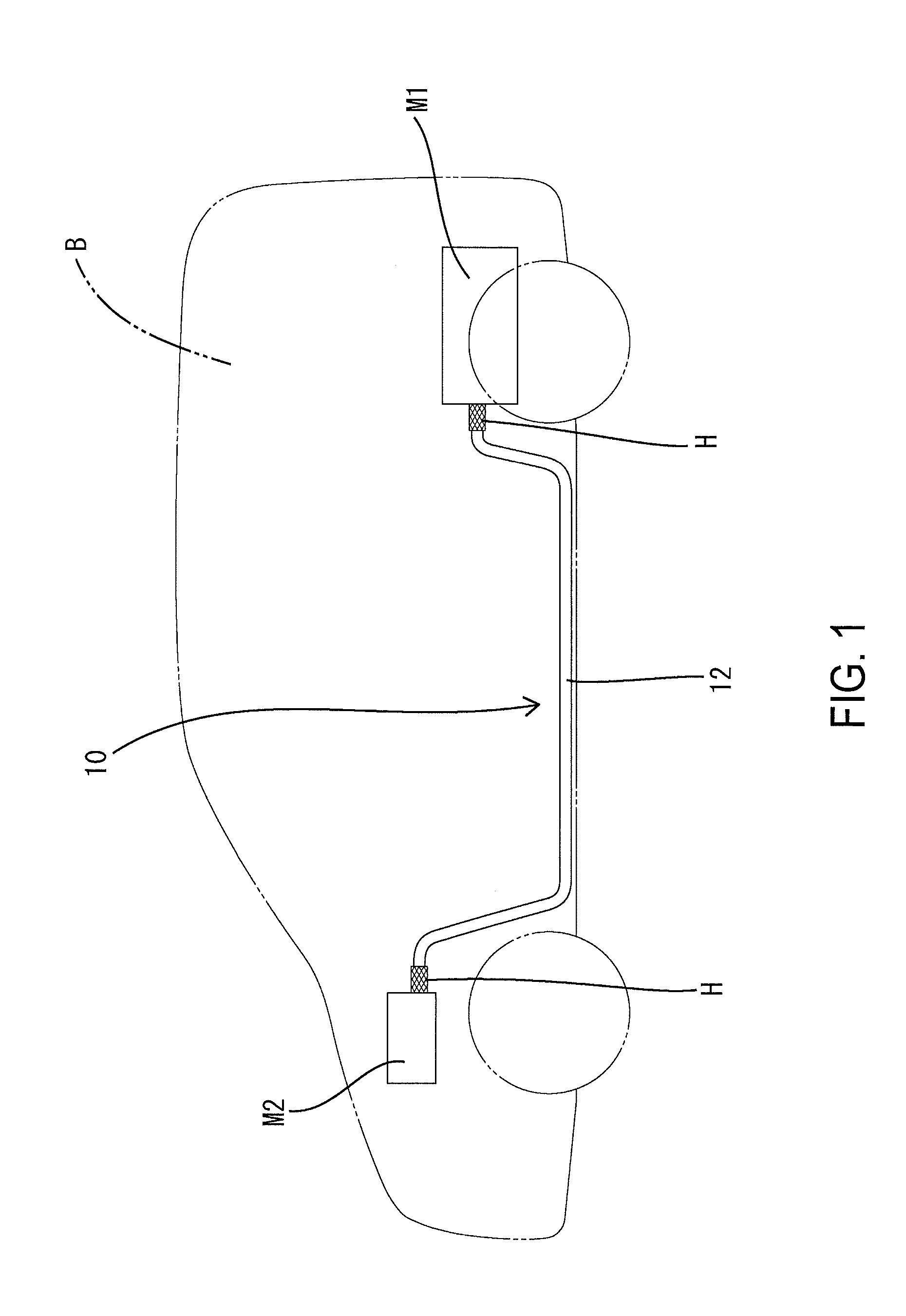
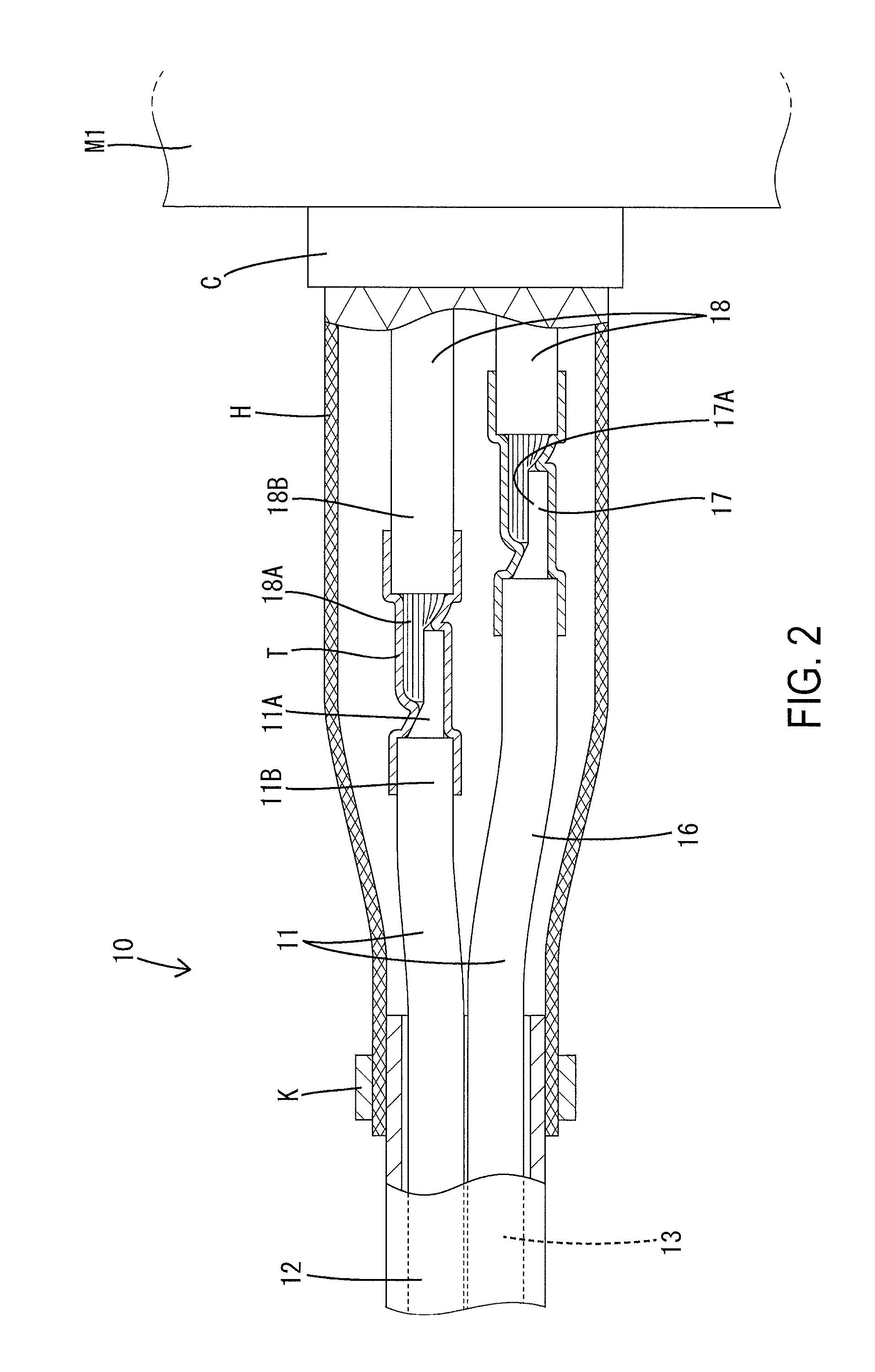
[0021]In a vehicle B such as a hybrid vehicle, a conductive path 10 of the present embodiment is routed under the bottom of the vehicle B in order to connect a device M1 installed in the back part of the vehicle B, such as a high-voltage battery, to a device M2 installed in the front part of the vehicle B, such as an inverter or fuse box (See FIG. 1). Note that each of the devices M1 and M2 is contained within a conductive shield case.

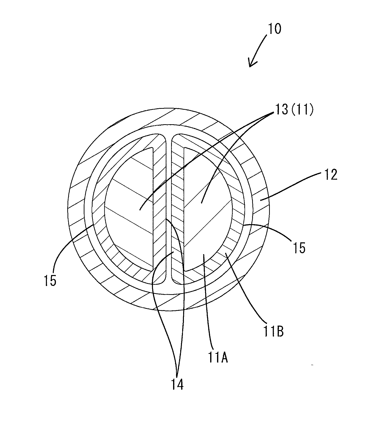
[0022]The conductive path 10 of the present embodiment is a shield conductive path that includes a pipe made of a metal (hereinafter referred to as “shield pipe 12”) with shield functionality into which multiple single-core electrical lines 11 (two in the present embodiment) are collectively inserted.

[0023]The electrical lines 11 are each a non-shielded electrical line that is made up of a single-core conductor 11A, which is made up of a single metal...


PUM


Abstract

A conductive path is provided that enables easily connecting stranded electrical lines to a plurality of single-core electrical lines collectively inserted into a pipe. The conductive path includes a plurality of single-core electrical lines, each being made up of one single-core conductor enveloped in an insulating sheathing, and a shield pipe into which the single-core electrical lines are collectively inserted. An end portion of each of the single-core conductors is a junction portion to which a stranded electrical line is to be connected, the stranded electrical line including a stranded conductor made up of a plurality of twisted individual wires, and an insulating sheathing that envelops the stranded conductor. The junction portions of the single-core electrical lines are arranged in the longitudinal direction with respect to each other outside of the shield pipe.

Description

TECHNICAL FIELD[0001]The exemplary embodiments relate to a conductive path.BACKGROUND ART[0002]Conventionally, in vehicles such as hybrid vehicles, there are cases in which multiple electrical lines are routed under the bottom of the vehicle in order to connect devices installed in the back part of the vehicle, such as high-voltage batteries, to devices installed in the front part of the vehicle, such as inverters and fuse boxes. In this regard, a technique is known in which electrical wires are inserted into a metallic pipe to not only electromagnetically shield them, but also protect them from interference by foreign objects (e.g., see JP 2012-222888A). The electrical lines are generally stranded electrical lines, which are stranded line conductors that are made up of multiple individual twisted wires and enveloped in an insulating sheathing, and can be freely bent for routing. Also, at the end portion region of the conductive path that is routed such that it weaves through the ga...

Claims


Application Information

Patent Timeline
IPC IPC(8): H02G3/04B60R16/02H01B7/00
CPCH02G3/0462H02G3/0406H01B7/0009B60R16/0215H02G3/0616
Inventor KANAGAWA, SHUICHI
Owner SUMITOMO WIRING SYST LTD
Why Eureka
Eureka Blog
Learn More