

Feedback for electronic pre-distortion in an optical transmitter
a technology of optical transmitter and electronic predistortion, which is applied in the direction of fiber transmission, electromagnetic transmission, electrical apparatus, etc., can solve the problems of performance penalty, exacerbated by relatively high modulation speed, etc., and achieve accurate estimation of device-specific signal distortion, reduce or cancel device-specific signal distortion, and reduce the cost of epd functionality
- Summary
- Abstract
- Description
- Claims
- Application Information
AI Technical Summary
Benefits of technology
Problems solved by technology
Method used
Image

Examples
Embodiment Construction
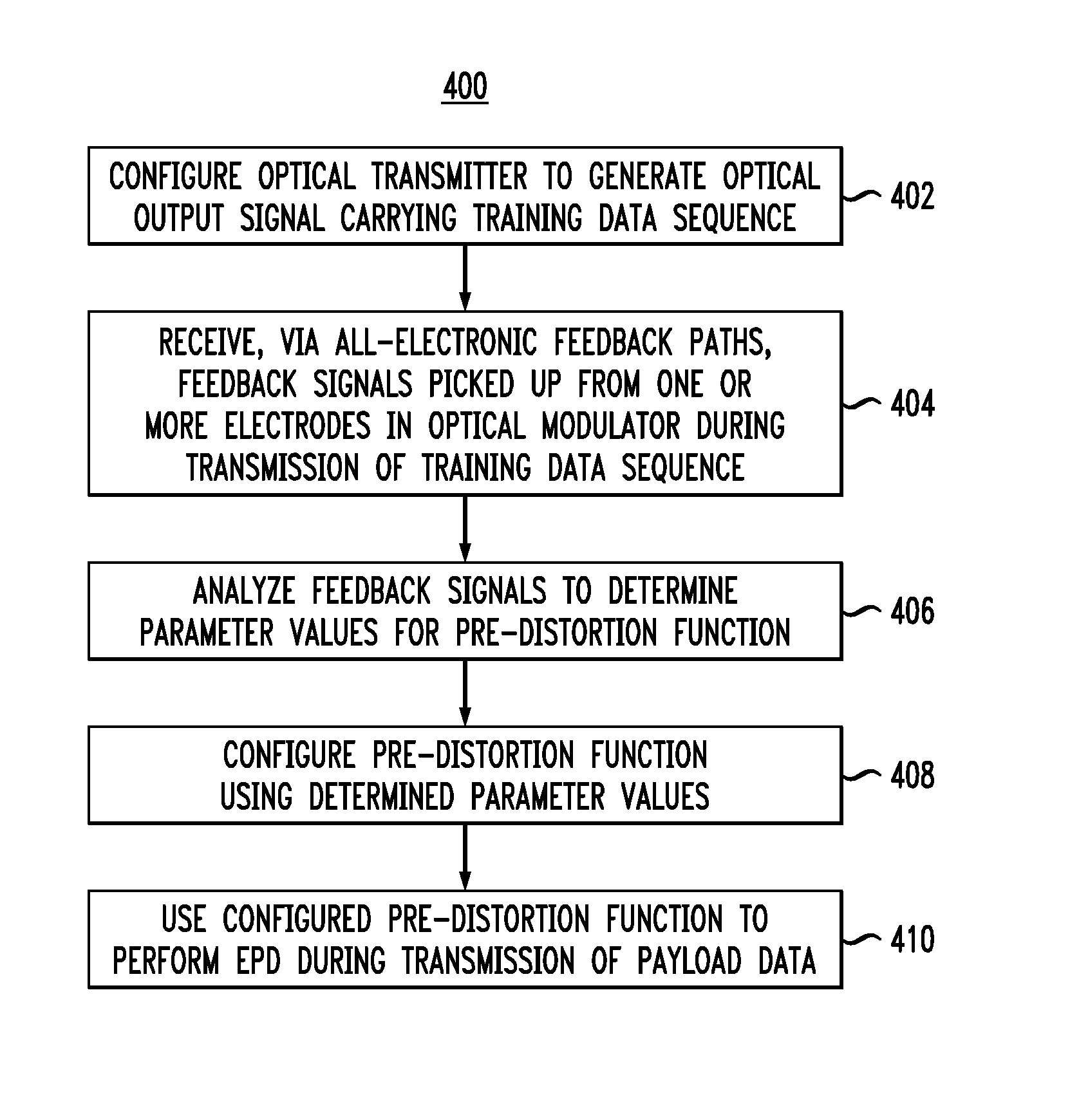
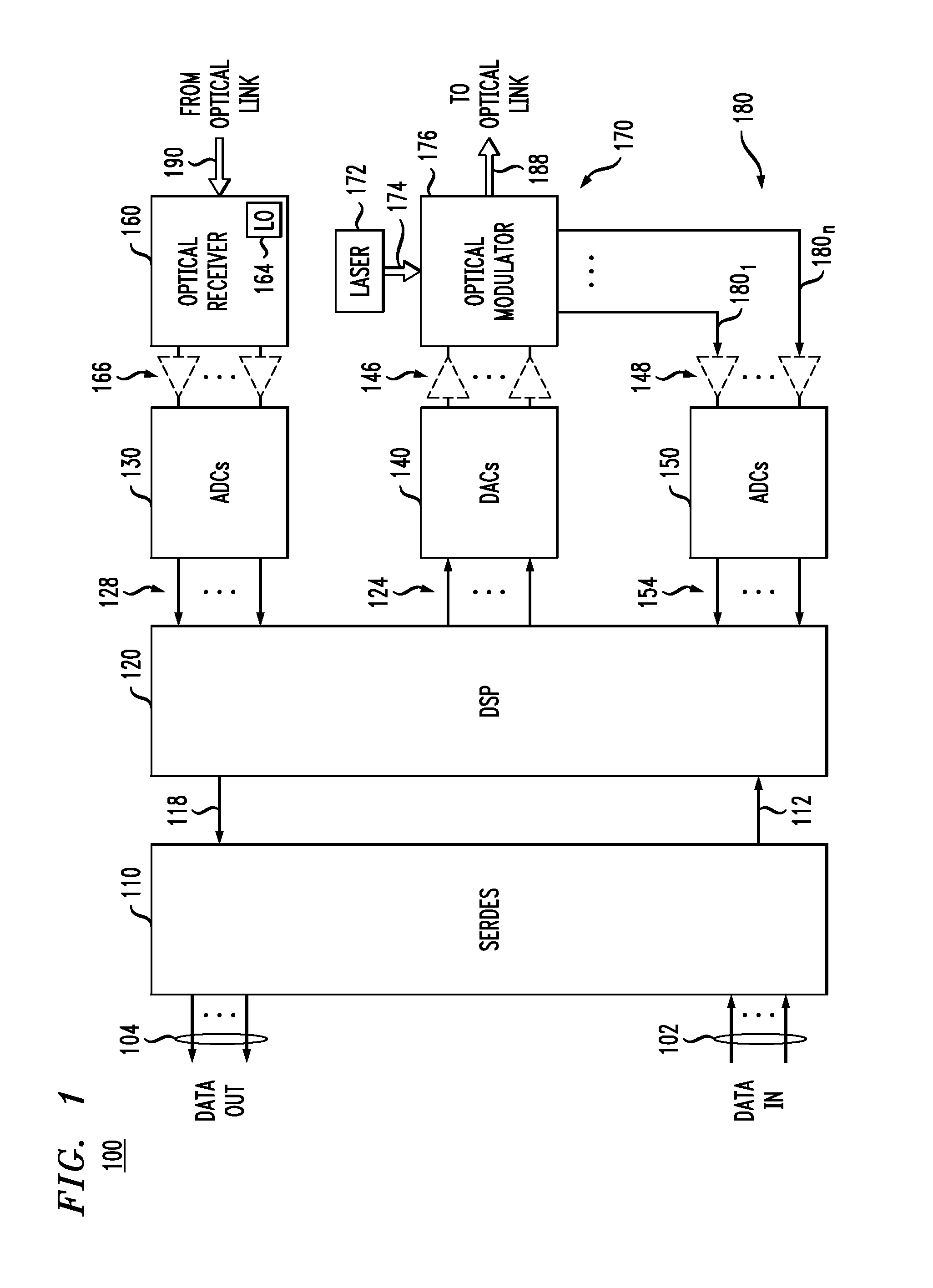
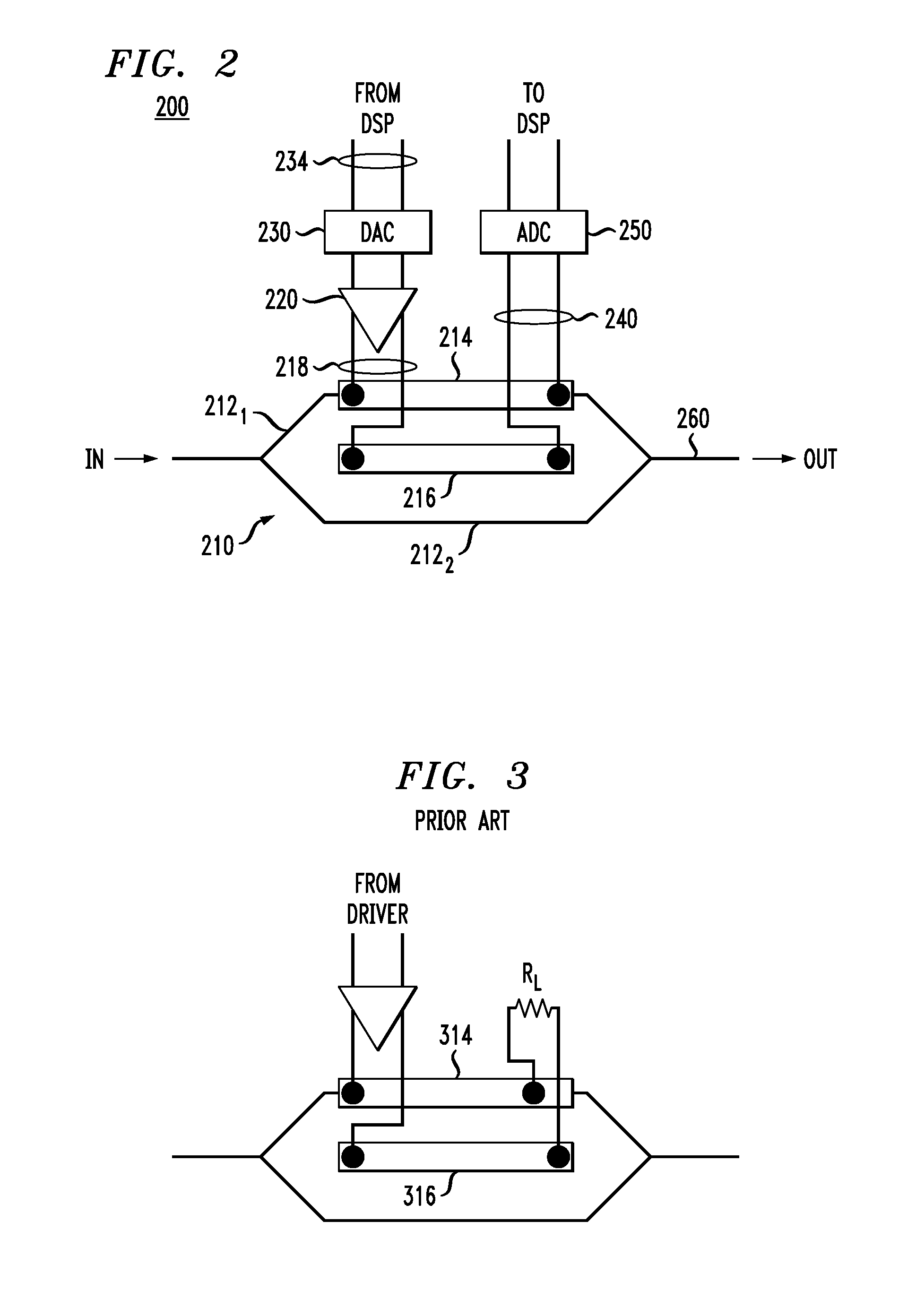
[0006]Disclosed herein are various embodiments of an optical transponder, in which one or more all-electronic feedback paths are used to obtain a relatively accurate estimate of the device-specific signal distortions in the transmitter portion thereof. The obtained estimate is used to enable the digital signal processor of the optical transponder to carry out electronic pre-distortion (EPD) that can significantly reduce or cancel these device-specific signal distortions without the use of detailed factory-calibration measurements or optics dedicated to feedback purposes. The use of all-electronic feedback paths may enable a beneficial reduction in the cost of the EPD functionality, e.g., by eliminating a significant extra cost associated with the implementation of optically generated feedback.
[0007]In some embodiments, the one or more all-electronic feedback paths may be used in parallel with one or more partially optical feedback paths.
[0008]According to one embodiment, provided is...
PUM
 Abstract
Description
Claims
Application Information