Display system, transmitting device, and method of controlling display system

a display system and transmitting device technology, applied in the field of display systems, can solve problems such as difficult to make the transmitting device, difficult to prevent, and increase the load of users

Inactive Publication Date: 2016-03-03
SEIKO EPSON CORP
View PDF53 Cites 4 Cited by
  • Summary
  • Abstract
  • Description
  • Claims
  • Application Information

AI Technical Summary

Benefits of technology

[0007]An advantage of some aspects of the invention is to provide a display system, a transmitting device, and a method of controlling the display system with which a setting of associating a transmitting device and a display device for wirelessly communicating with each other with each other can surely be achieved as intended when performing the setting,

Problems solved by technology

However, it has not necessarily been easy to make the transmitting device and the display device correspond to each other as intended to achieve the pairing.
However, since the operation becomes troublesome and complicated, the load of the user problematically increases.
Further, in the case in which a change in setting procedure is restricted due to the standard or the specification of the communication protocol, it is not achievable to prevent the situation described above by changing the procedure.

Method used


Image

  • Display system, transmitting device, and method of controlling display system
  • Display system, transmitting device, and method of controlling display system
  • Display system, transmitting device, and method of controlling display system

Examples


first embodiment

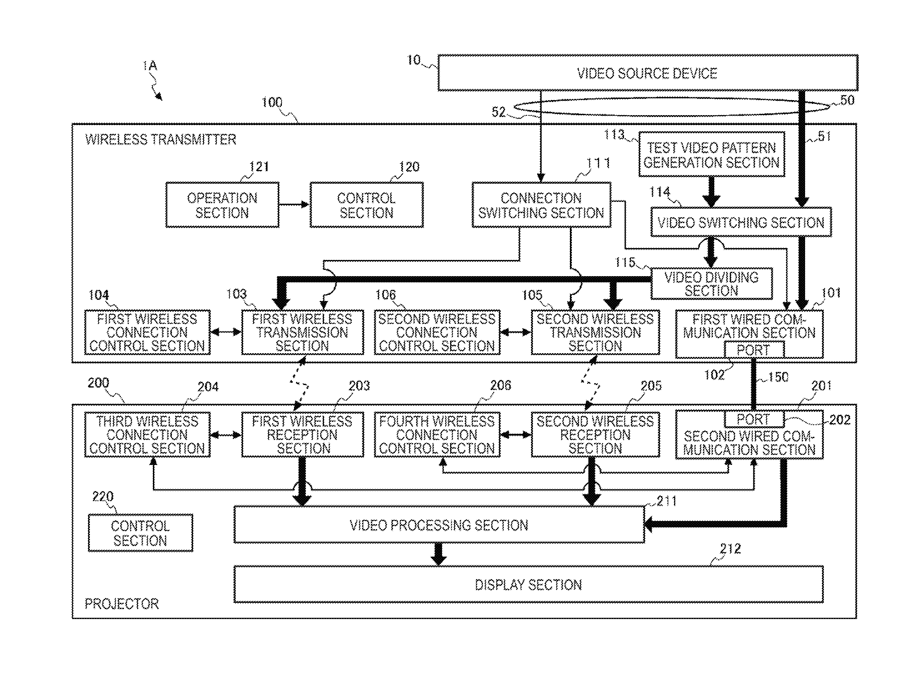
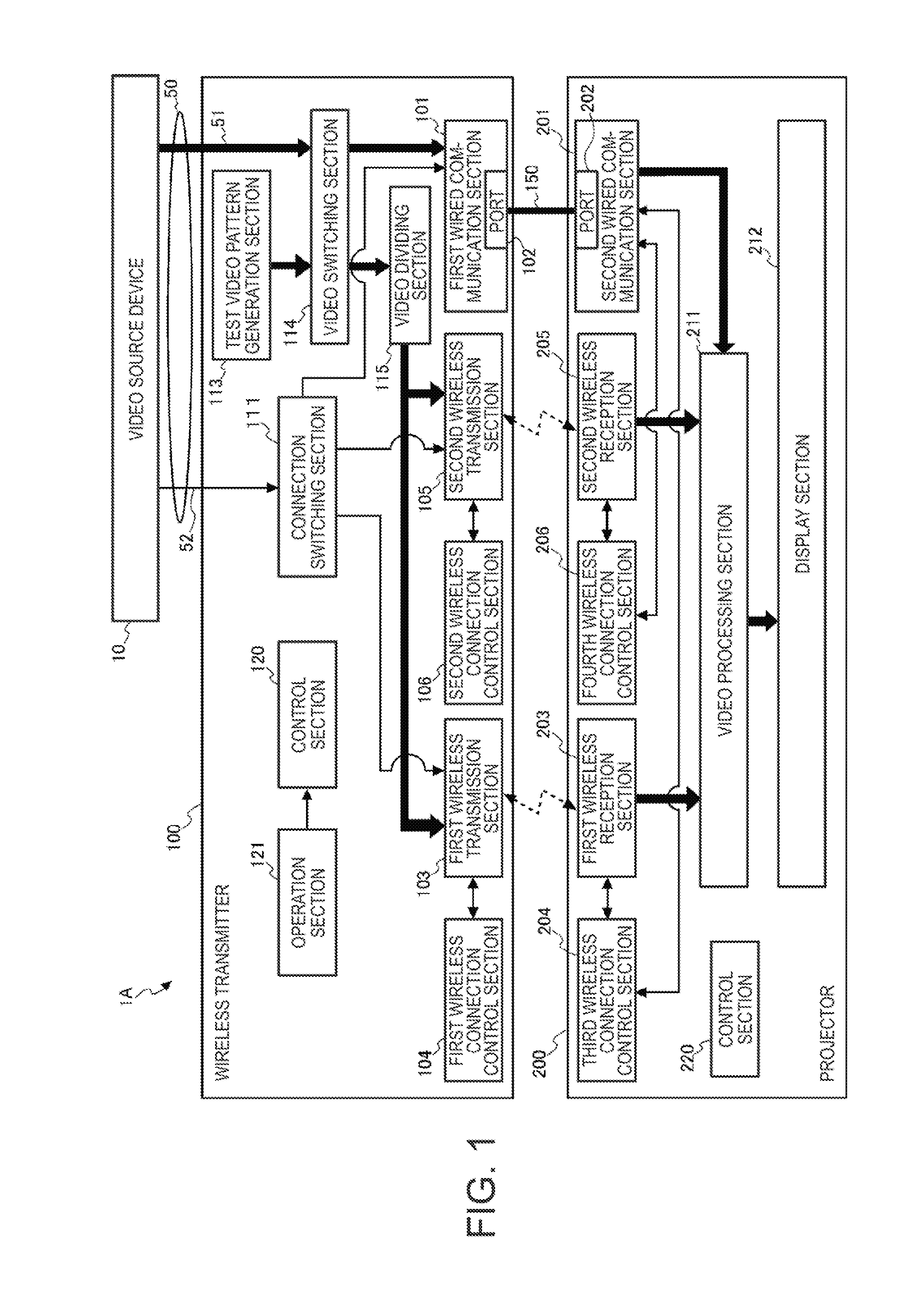
[0032]FIG. 1 is a diagram showing a configuration, of a display system 1A according to a first embodiment.

[0033]The display system 1A is provided with a wireless transmitter 100 and a projector 200. The wireless transmitter 100 is connected to the projector 200 with a cable 150 in a wired manner. Further, the wireless transmitter 100 is connected to the projector 200 with the wireless communication.

[0034]The wireless transmitter 100 is connected to a video source device 10 via a cable 50. The display system 1A is a system, in which the wireless transmitter 100 transmits video data, output by the video source device 10 to the projector 200, and the projector 200 projects (displays) an image based on the video data.

[0035]The video source device 10 is a device for supplying the display system 1A with the video data, and is connected to the wireless transmitter 100 via the cable 50 as described above. The video source device 10 is a video output device such as a DVD (digital versatile d...

second embodiment

[0131]FIG. 3 is a diagram showing a configuration of a display system 1B according to a second embodiment to which the invention is applied. It should be noted that the sections configured similarly to the first embodiment out of the functional sections shown in FIG. 3 will be denoted with the same reference symbols, and the explanation thereof will be omitted.

[0132]The display system 1B is provided with a wireless transmitter 170 and a projector 250.

[0133]Similarly to the wireless transmitter 100 of the first embodiment, the wireless transmitter 170 is provided with the first wired communication section 101, the connection switching section 111, the test video pattern generation section 113, the video switching section 114, the control section 120, and the operation section 121. Further, the wireless transmitter 170 is different from the wireless transmitter 100 in the point that one wireless transmission section 107 and one wireless connection control section 108 are provided.

[013...


PUM


Abstract

A display system includes a transmitting device adapted to transmit video data, and a display device adapted to display a picture based on the video data. The transmitting device includes a wired connection section, and a wireless transmission section adapted to wirelessly transmit the video data. The display device includes a wired connection section, and a wireless reception section adapted to receive the video data, the transmitting device and the display device transmit and receive identification information used in a case in which the wireless transmission section and the wireless reception section perform communication in a state in which the wired connection section of the transmitting device and the wired connection, section of the display device are connected to each other with wire, and perform pairing adapted to associate the transmitting device and the display device with each otter based on the identification information transmitted and received.

Description

[0001]The entire disclosure of Japanese Patent Application No. 2014-174860, filed Aug. 29, 2014 is expressly incorporated by reference herein.BACKGROUND[0002]1. Technical Field[0003]The present invention relates to a display system, a transmitting device, and a method of controlling the display system.[0004]2. Related Art[0005]In the past, there has been known a method of transmitting data to a display device using wireless communication (see, e.g., JP-A-2013-117860 (Document 1)). In Document 1, there is described a configuration of transmitting image information to a projector as a display device from a transmitter compatible with WirelessHD (registered trademark).[0006]In the case of wirelessly transmitting data to the display device as described in Document 1, there is required a setting called pairing for associating the transmitting device on the transmission side and the display device with each other as communication counterparts. In the past, the pairing has been achieved by...

Claims


Application Information

Patent Timeline
Patent Type & Authority Applications(United States)
IPC IPC(8): H04N5/38H04N7/015
CPCH04N7/015H04N5/38G09G5/006G09G2370/12G09G2370/16G09G2370/22
Inventor NAGUMO, TAKASHIHASHIMOTO, HIROYUKI
Owner SEIKO EPSON CORP
Why Eureka
Try Eureka