Display apparatus and manufacturing method thereof

a technology of display apparatus and manufacturing method, which is applied in the direction of electric apparatus casings/cabinets/drawers, casings with display/control units, instruments, etc., can solve the problems of low yield rate, difficult to implement in reality, and high cos

Active Publication Date: 2016-03-03
ELECTRONICS & TELECOMM RES INST
View PDF15 Cites 7 Cited by
  • Summary
  • Abstract
  • Description
  • Claims
  • Application Information

AI Technical Summary

Benefits of technology

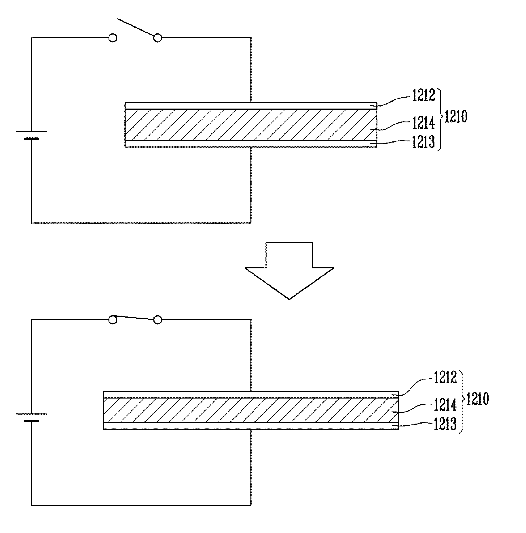
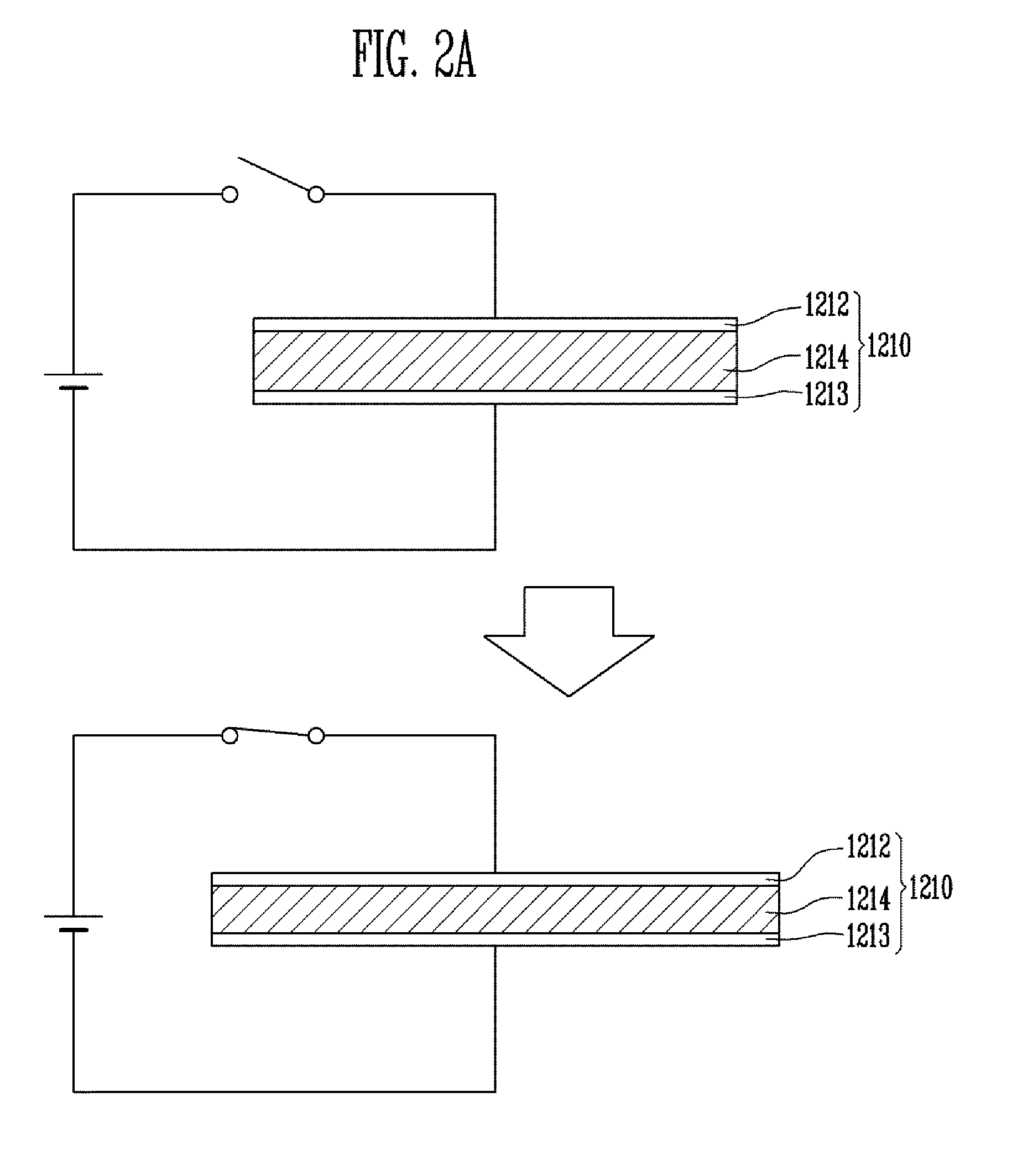
[0011]The present disclosure has an effect of providing a display apparatus wherein its curvature may be adjusted, and then the curvature may be maintained without having to apply power continuously, and a manufacturing method thereof.
[0012]Furthermore, the present disclosure has an effect of providing a display apparatus which uses a polymer layer that changes its state according to temperature so that the polymer layer may be heated to have ductility when adjusting the curvature of the display apparatus, and then once the display apparatus is curved to a desired curvature, the polymer layer may be cooled down so that the curvature is maintained even when power is not applied continuously, and a manufacturing method thereof.

Problems solved by technology

However, such a technology not only costs a lot to maintain a constant cell gap between two pre-molded substrates, but it also has a very low yield rate, and such a technology is difficult to implement in reality.
Furthermore, another disadvantage is that in order to provide different curvatures of the display apparatus, a separate molding tool must be manufactured for each product, increasing the manufacturing cost.
However, in this method, it is difficult to adjust the curvature after eliminating the tensile force, which makes it very difficult to manufacture a display panel having a desirable curvature.
However, although such a technology may curve the display panel to have a desired curvature, it has a disadvantage that it has to consume power continuously to maintain that curvature.

Method used


Image

  • Display apparatus and manufacturing method thereof
  • Display apparatus and manufacturing method thereof
  • Display apparatus and manufacturing method thereof

Examples


Embodiment Construction

[0022]Hereinafter, embodiments will be described in greater detail with reference to the accompanying drawings. Embodiments are described herein with reference to cross-sectional illustrations that are schematic illustrations of embodiments (and intermediate structures). As such, variations from the shapes of the illustrations as a result, for example, of manufacturing techniques and / or tolerances, are to be expected. Thus, embodiments should not be construed as limited to the particular shapes of regions illustrated herein but may include deviations in shapes that result, for example, from manufacturing. In the drawings, lengths and sizes of layers and regions may be exaggerated for clarity. Like reference numerals in the drawings denote like elements.

[0023]Terms such as ‘first’ and ‘second’ may be used to describe various components, but they should not limit the various components. Those terms are only used for the purpose of differentiating a component from other components. For...


PUM


Abstract

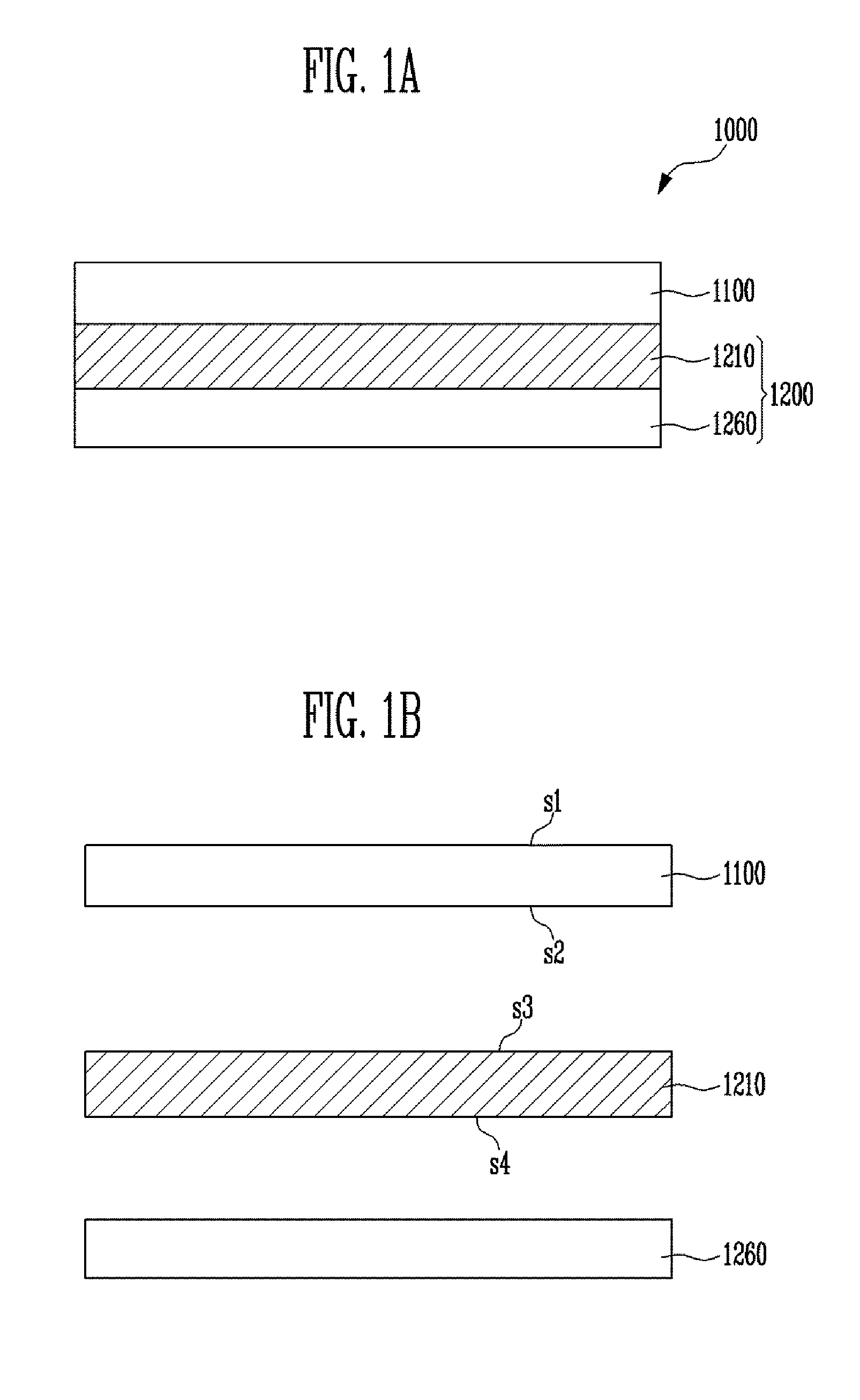
Provided herein a display apparatus including a display panel including a first surface for displaying information and a second surface disposed opposite to the first surface, and where a curvature is formed as a physical force is applied; and a curvature changing unit bonded to at least a portion of the second surface, wherein the curvature changing unit includes a first actuator unit configured to curve the display panel when a voltage is applied and a fixing unit configured to fixate the first actuator unit.

Description

CROSS-REFERENCE TO RELATED APPLICATION[0001]The present application claims priority to Korean patent application number 10-2014-0111737, filed on Aug. 26, 2014, the entire disclosure of which is incorporated herein in its entirety by reference.BACKGROUND[0002]1. Field of Invention[0003]Various embodiments of the present disclosure relate to a display apparatus and a manufacturing method thereof, and more particularly, to a display apparatus of which the curvature may be changed if necessary by a user and of which the changed condition may be maintained, and a manufacturing method thereof.[0004]2. Description of Related Art[0005]As display technologies develop to cathode ray tubes, displays, liquid displays, and organic light-emitting displays and so forth, the performance, size, and function of displays are diversifying. Especially, due to the recent market demand for flexible displays that may be bent or curved, proactive research and development is underway on such technologies.[0...

Claims


Application Information

Patent Timeline
Patent Type & Authority Applications(United States)
IPC IPC(8): H05K5/02H05K5/00
CPCH05K5/0017H05K5/02G02F1/133305H10K50/80H10K2102/311
Inventor PARK, SUN, TAKKYUNG, KI, UKYUN, SUNG, RYULNAM, SAE, KWANGPARK, BONG, JE
Owner ELECTRONICS & TELECOMM RES INST
Why Eureka
Try Eureka