Suspension device for tracked vehicle

Active Publication Date: 2016-03-10
BAE SYSTEMS HAGGLUND AKTIEBOLAG
View PDF10 Cites 32 Cited by
  • Summary
  • Abstract
  • Description
  • Claims
  • Application Information

AI Technical Summary

Benefits of technology

[0023]In one embodiment of the suspension device, said track assembly suspension configuration comprises a front trailing arm configuration and a rear trailing arm configuration for the respective track assembly, wherein the front trailing arm configuration at one end is articulately connected at a lower attachment of a front region of said centre beam and at the other end at a front region of said track support beam, and wherein the rear trailing arm configuration at one end is articulately connected at a lower attachment of a rear region of said centre beam and in the another end at a rear region of said track support beam. Hereby an effective track assembly suspension structure for improved comfort and mobility as well as effective absorption of shock is provided.
[0024]In one embodiment of the suspension device, said front hydraulic cylinder is at one end pivotally connected to a front side region of said centre beam and at the other end to a front region of said track support beam, in connection with said front trailing arm configuration, and wherein said rear hydraulic cylinder at one end is pivotally connected to a rear side region of said centre beam and at the other end to a rear region of said track support beam. Hereby an effective track assembly suspension structure for improved comfort and mobility is provided.
[0025]In one embodiment of the suspension device, at least one of said

Problems solved by technology

For larger obstacles and rough terrain such support wheel suspension is not effective to the same extent, resulting in that comfort is not maint

Method used


Image

  • Suspension device for tracked vehicle
  • Suspension device for tracked vehicle
  • Suspension device for tracked vehicle

Examples


Embodiment Construction

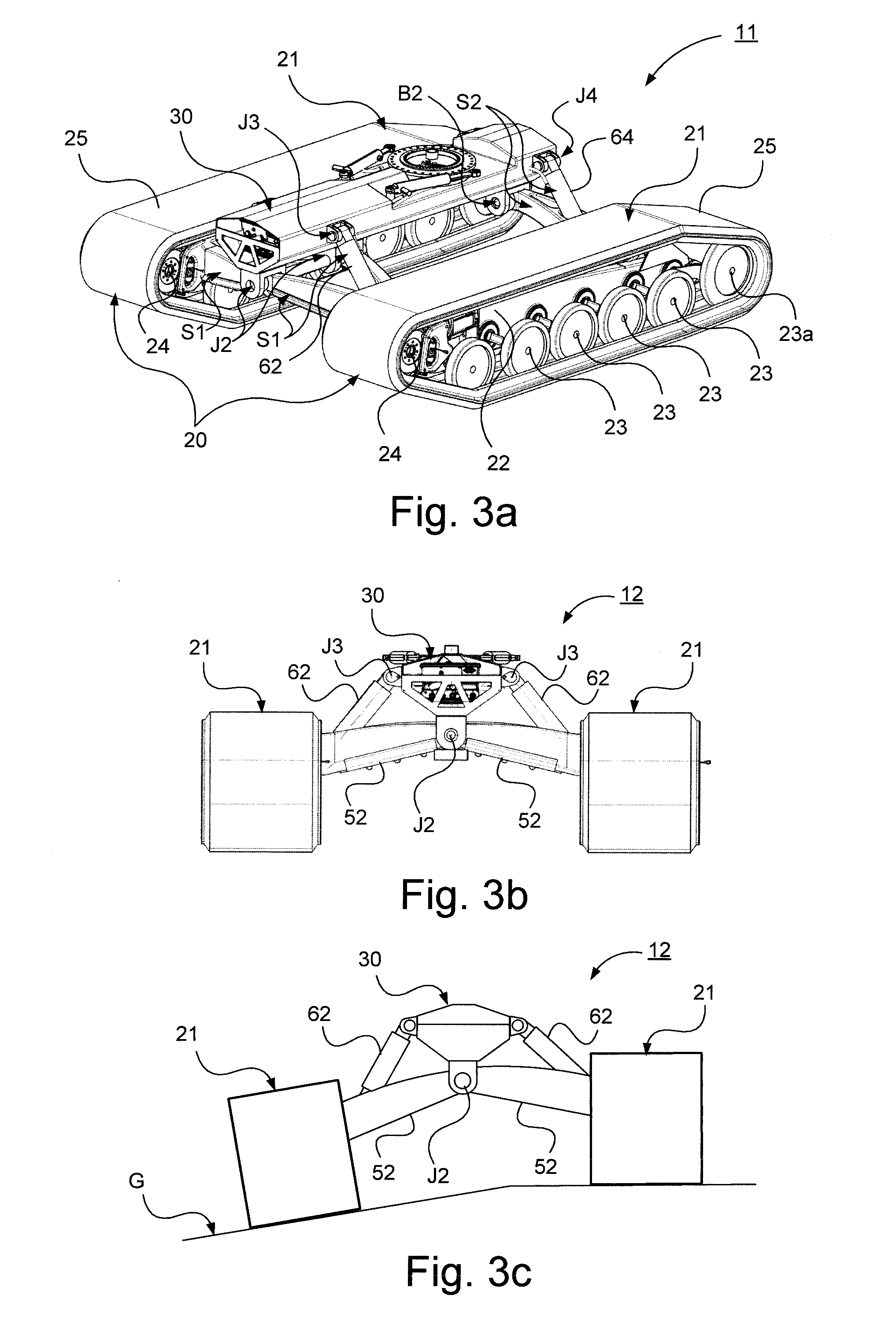
[0041]Herein, the term “link” refers to a communication link which may be a physical connection, such as an opto-electronic communication cable, or a non-physical connection, such as a wireless connection, for example a radio or microwave link.

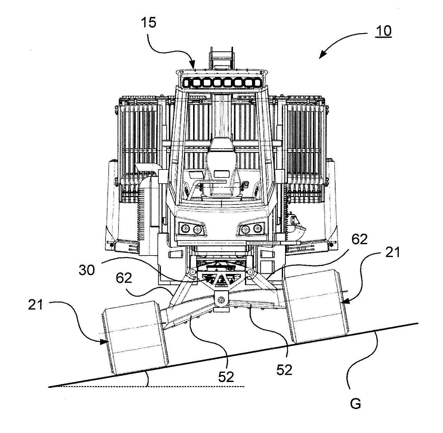
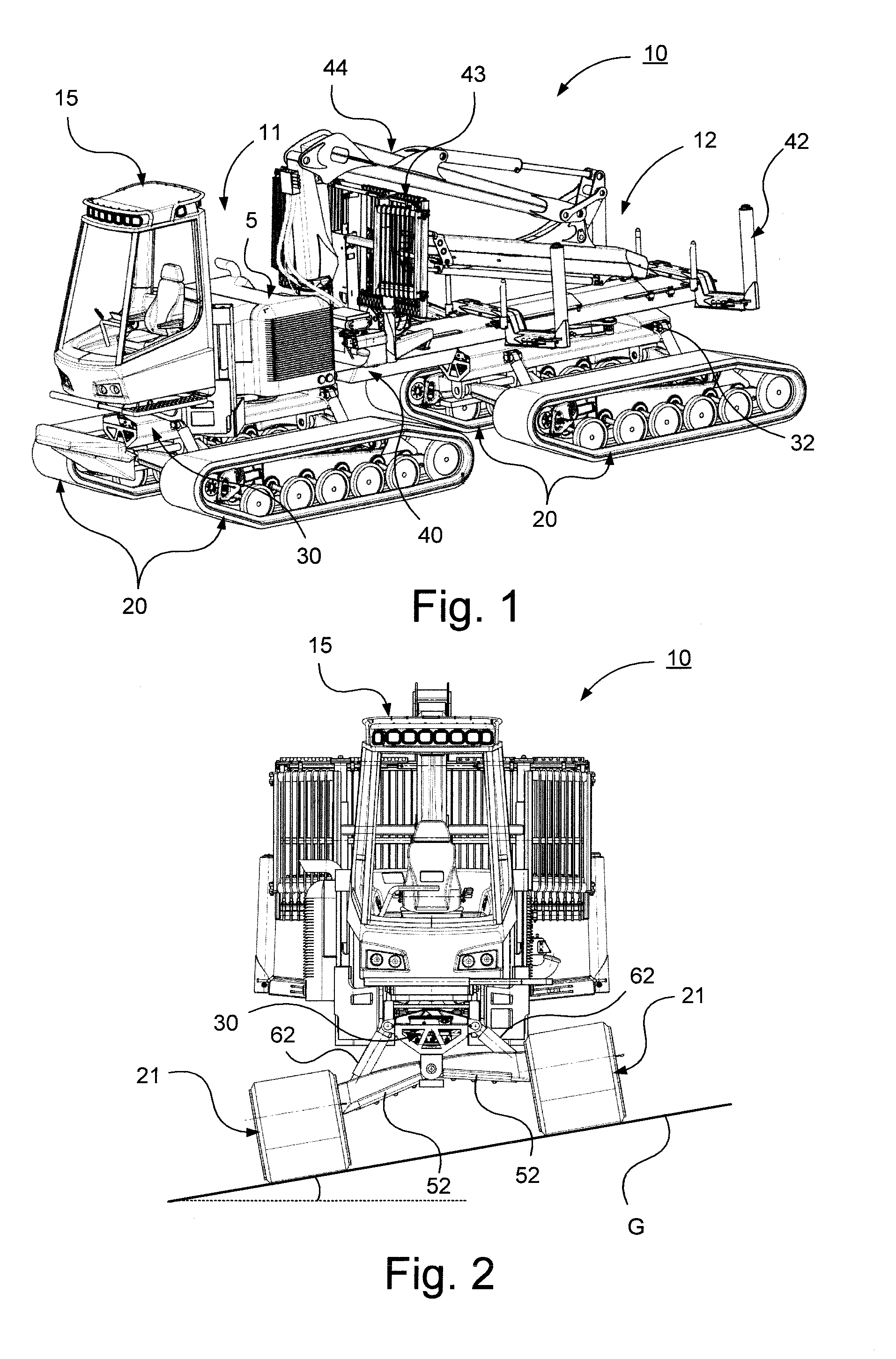
[0042]Herein, the term “track support beam” refers to a structural element arranged to support ground-engaging means such as e.g. an endless track as well as drive wheel and support wheels.

[0043]Herein, the term “track assembly” refers to a unit of the tracked vehicle comprising track support beam, drive wheel and support wheels as well as a circumferential endless track, which unit is arranged to comprise ground-engaging means and configured to propel the vehicle and thus form at least part of a drive unit of the tracked vehicle.

[0044]Herein, the term “track assembly pair” refers to opposite track assemblies of a vehicle unit of the vehicle, one track assembly constituting a right track assembly and the opposite track assembly constituting a ...


PUM


Abstract

The invention relates to a suspension device for tracked vehicles, which vehicle comprises at least one pair of track assemblies, where each track assembly of the pair of track assemblies comprises a track support beam, at least one drive wheel, a plurality of support wheels and an endless track, wherein said at least one drive wheel and said plurality of support wheels are rotatably secured to said track support beam. Said at least one drive wheel is arranged to drive said endless track running over the at least one drive wheel and said plurality of support wheels. The suspension device comprises a first suspension configuration constituting a support wheel suspension configuration configured to resiliently secure said support wheels to said track support beam, and a second suspension configuration configured to connect said track assembly pair with a centrally arranged center beam. The invention also relates to a tracked vehicle.

Description

CROSS REFERENCE TO RELATED APPLICATIONS[0001]This application is a U.S. National Stage patent application of PCT / SE2014 / 050563, filed on May 7, 2014, which claims priority to Swedish Patent Application No. 1350562-3, filed on May 8, 2013, the entire contents of which are incorporated herein by reference.FIELD OF THE INVENTION[0002]The present invention relates to a suspension device for tracked vehicles. The present invention also relates to a tracked vehicle.BACKGROUND OF THE INVENTION[0003]Tracked vehicles are provided with so called support wheel suspension to improve mobility and comfort. In such a tracked vehicle, the vehicle has a pair of track assemblies; in articulated tracked vehicles each vehicle unit has a pair of track assemblies. Each track assembly in the pair of track assemblies comprises a track support beam, at least one drive wheel, a plurality of support wheels and an endless track. Said at least one drive wheel and said plurality of support wheels are rotatably s...

Claims


Application Information

Patent Timeline
IPC IPC(8): B62D55/104B62D55/108
CPCB62D55/108B62D55/104B62D55/112B62D55/116B62D55/065B62D55/1125B60G2300/32B60G3/08B60G3/145B60G17/0165B60G21/073B60G2200/13B60G2200/14B60G2206/11B60G2206/124B60G2300/083B60G2800/019B60G5/00B60G21/00B62D55/06
Inventor HELLHOLM, BJORNNORDBERG, BJORN
Owner BAE SYSTEMS HAGGLUND AKTIEBOLAG
Why Eureka
Try Eureka