Series-operation Toilet System with Hydraulic Seat Lifting and Flushing

a toilet system and hydraulic seat technology, applied in the field of toilets, assistive devices, flushing devices, can solve the problems of user physical limitations weighing in favor of use, and achieve the effects of smooth device operation, removal of physical limitations of users, and smooth application of similarly powerful for

Active Publication Date: 2016-03-17
WAIKAS II JOHN P
View PDF5 Cites 0 Cited by
  • Summary
  • Abstract
  • Description
  • Claims
  • Application Information

AI Technical Summary

Benefits of technology

[0010]One reason to use water rather than other force-conveying systems, such as a user-driven tension-carrying wire or a force-translating linkage system, is to take advantage of the force already provided to a toilet by the inflow of water pressure. The continuous availability of force from water pressure makes smooth operation of the device independent of the ability of a user to smoothly apply similarly powerful force.
[0011]Another contemplated advantage of using water is that removes the physical limitations of the user from negatively affecting the reliability of correctly using of the invention. Certainly, the physical limitations of a user weigh in favor of using an independently-available force that does not require the user to provide the forces necessary to lift a seat or flush a toilet.

Problems solved by technology

Certainly, the physical limitations of a user weigh in favor of using an independently-available force that does not require the user to provide the forces necessary to lift a seat or flush a toilet.

Method used


Image

  • Series-operation Toilet System with Hydraulic Seat Lifting and Flushing
  • Series-operation Toilet System with Hydraulic Seat Lifting and Flushing
  • Series-operation Toilet System with Hydraulic Seat Lifting and Flushing

Examples


Embodiment Construction

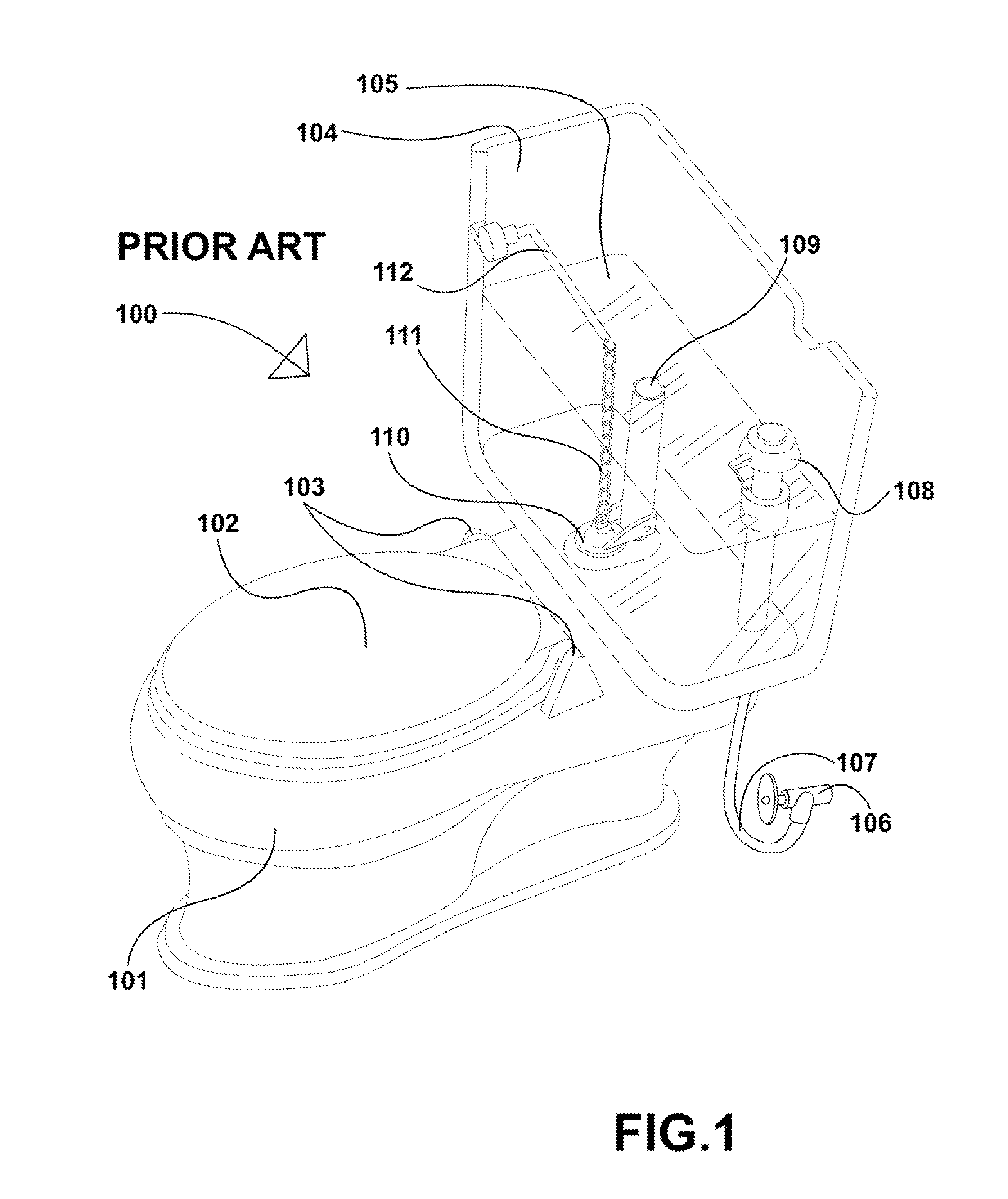
[0017]Referring now to FIG. 1, a prior art toilet 100 is shown. It comprises a base 101, a lid 102 connected to the base 101 by a lid hinge 103, and a tank 104, filled with water 105. The tank is fed by a water source, depicted as water spigot 106, which provides fill water to the tank 104 via a water feed line 107 and a tank fill valve 108. The volume of the water 105 retained in the tank 104 is limited by the height of an overflow tube 109, dictating the height of the water level in the tank 104. The water 105 the tank is flushable into the base 101 by lifting a tank flush flap 110. The tank flush flap 110 is connected to a flush lever 112 by a chain 111. Sufficient force applied to the flush lever 112 translates force through the chain 111 to open the flush flap 110.

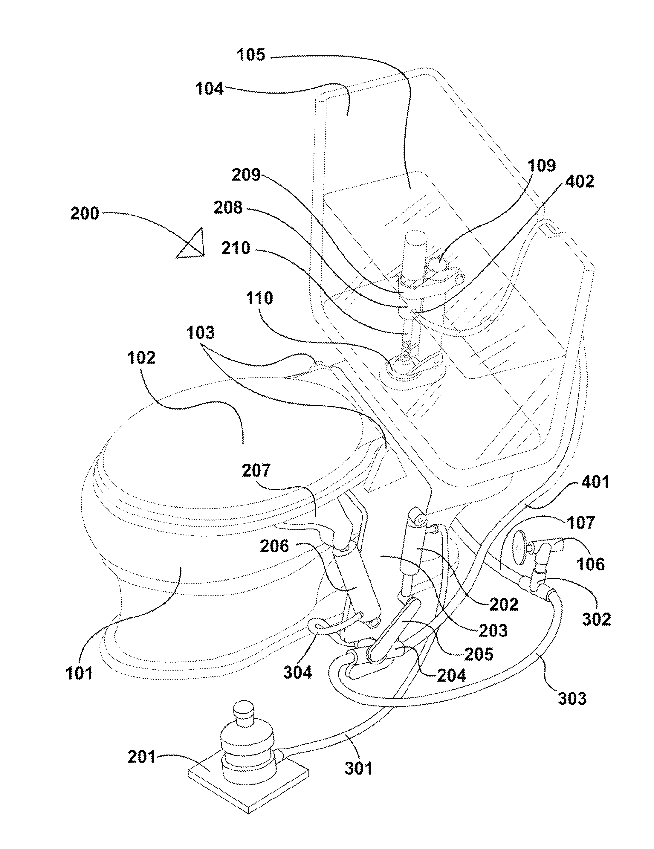
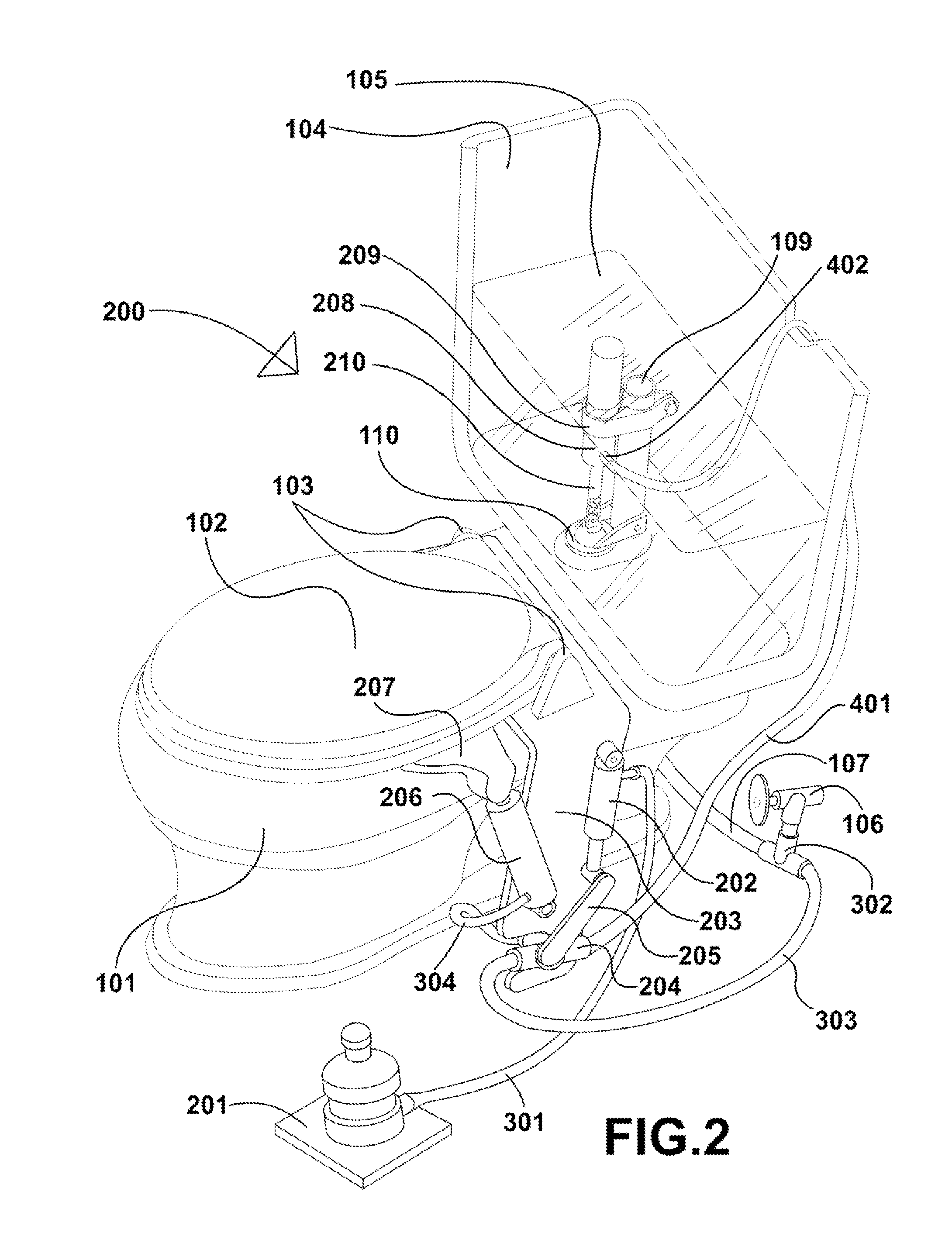
[0018]FIGS. 2-5 depict toilet system embodiments of the present invention that providing lift and flush mechanisms that comprise some components similar to those found in the prior art toilet of FIG. 1, as well as ful...


PUM


Abstract

The invention is a series-operation seat-lifting and flush system applicable to conventional residential gravity-powered flap-released water-tank toilets. The system first lifts the seat with a hydraulic cylinder and then lowers the seat and flushes the toilet by venting the hydraulic cylinder to a mechanism connected to the flush-flap. Operation of a closed-fluid-circuit floor-trigger causes water to be diverted from the existing source of water to drive the mechanism.

Description

RELEVANT FIELDS OF ART[0001]The invention relates to the fields of toilets, assistive devices, flushing devices, water catch cans, lever systems driven by varying or accumulating fluid loads, and water actuated pistons.BACKGROUND OF THE INVENTION[0002]The water-flushed toilet is one of the most significant improvements of sanitation in human history. With its proliferation, propagation of many diseases was curbed commensurately. Before the water-flushed toilet, common practice was simply to dispose liquid waste into the immediately available streets, where it would accumulate or flow into the immediately adjacent water resources. Since its use became widespread, the water-flushed toilet provided an avenue for waste to be moved to locations remote to human population centers.[0003]However, in terms of advancing the objective of healthy home use, there remain areas that are begging for improvement. One is furthering sanitary handling of the toilet seat which sits directly over the bow...

Claims


Application Information

Patent Timeline
Patent Type & Authority Applications(United States)
IPC IPC(8): A47K13/10
CPCA47K13/10
Inventor WAIKAS, II, JOHN, P.
Owner WAIKAS II JOHN P
Why Eureka
Try Eureka