Eureka AIR delivers breakthrough ideas for toughest innovation challenges, trusted by R&D personnel around the world.

Method, ECG measuring device, and medical imaging device for determining an r-wave in an ECG signal

Active Publication Date: 2016-03-17
SIEMENS AG
View PDF5 Cites 1 Cited by
  • Summary
  • Abstract
  • Description
  • Claims
  • Application Information

AI Technical Summary

Benefits of technology

The technical effect of this patent is to provide a way to detect R-waves that is not affected by the person's breathing position.

Problems solved by technology

This determination is made difficult, however, for example where an ECG measuring device is used within a magnetic resonance scanner, due to T-wave superelevations that occur in the magnetic field.
Magnetic fields that change over time, as are used in a magnetic resonance scanner as magnetic gradient fields for spatial encoding, also still constitute a further, significant problem for reliable ECG signal measuring.
These interferences are highly undesirable.
Due to their often similar form for example, the interference signals can be erroneously interpreted as an R-wave and therefore incorrectly trigger recording of a magnetic resonance image.
This regularly leads to a significant deterioration in the image quality.
A further problem that occurs independently of the imaging modality used is that of an examination object holding their breath in order to prevent or minimize movement artifacts in the imaging of a heart.
Increased amplitudes of R-waves during a breath-holding phase make reliable R-wave detection difficult.
Successful detection of R-waves is made difficult as a result.

Method used


Image

  • Method, ECG measuring device, and medical imaging device for determining an r-wave in an ECG signal
  • Method, ECG measuring device, and medical imaging device for determining an r-wave in an ECG signal
  • Method, ECG measuring device, and medical imaging device for determining an r-wave in an ECG signal

Examples


Embodiment Construction

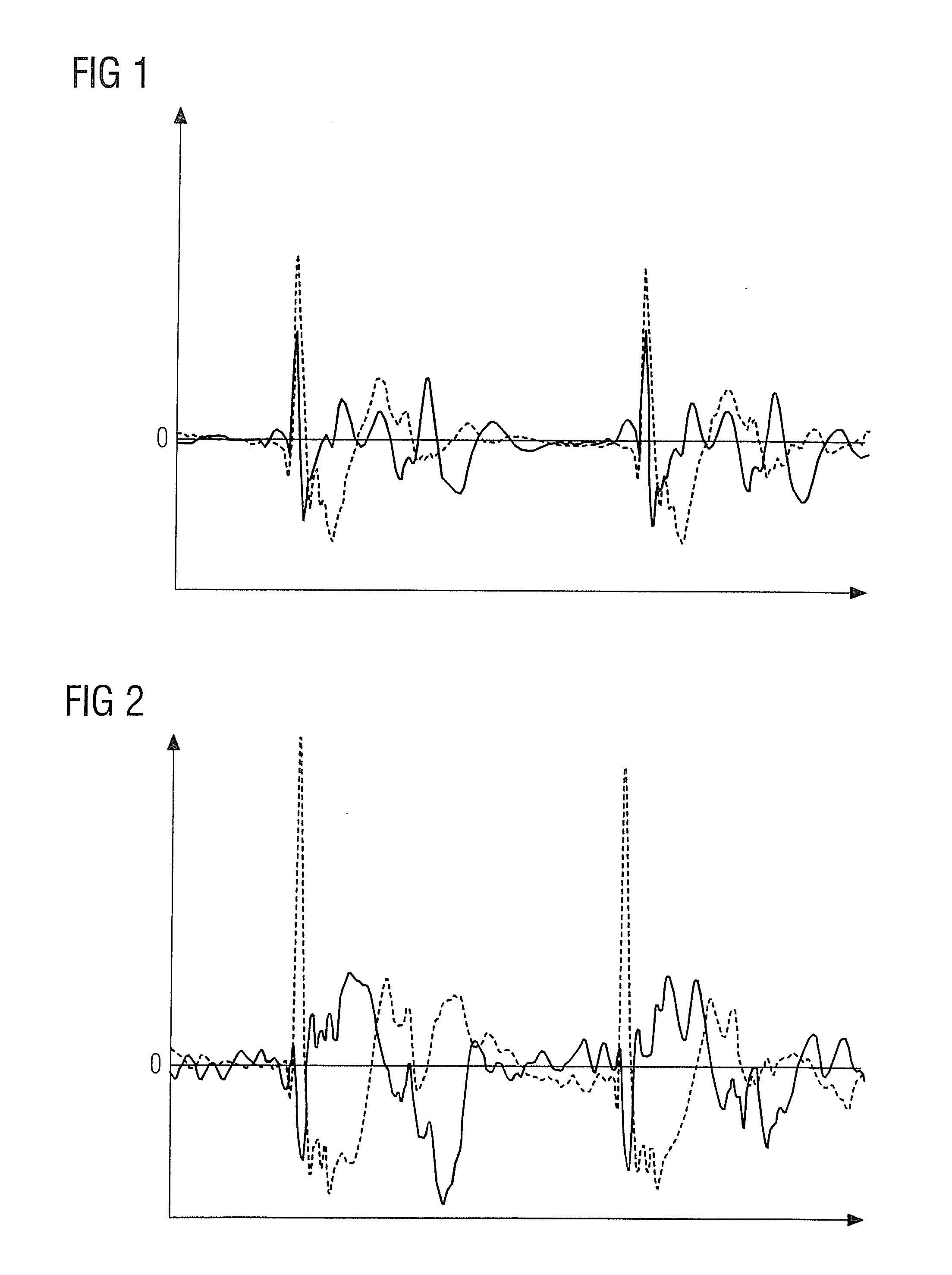
[0111]FIG. 1 shows a curve of an ECG signal having two channels over time in the case of shallow breathing of an examination object. The ECG signal is shown as the voltage U over time. Characteristic curves of the ECG signal are identified according to Einthoven by the letters P, Q, R, S and T and conventionally reproduce the various phases of a heartbeat.

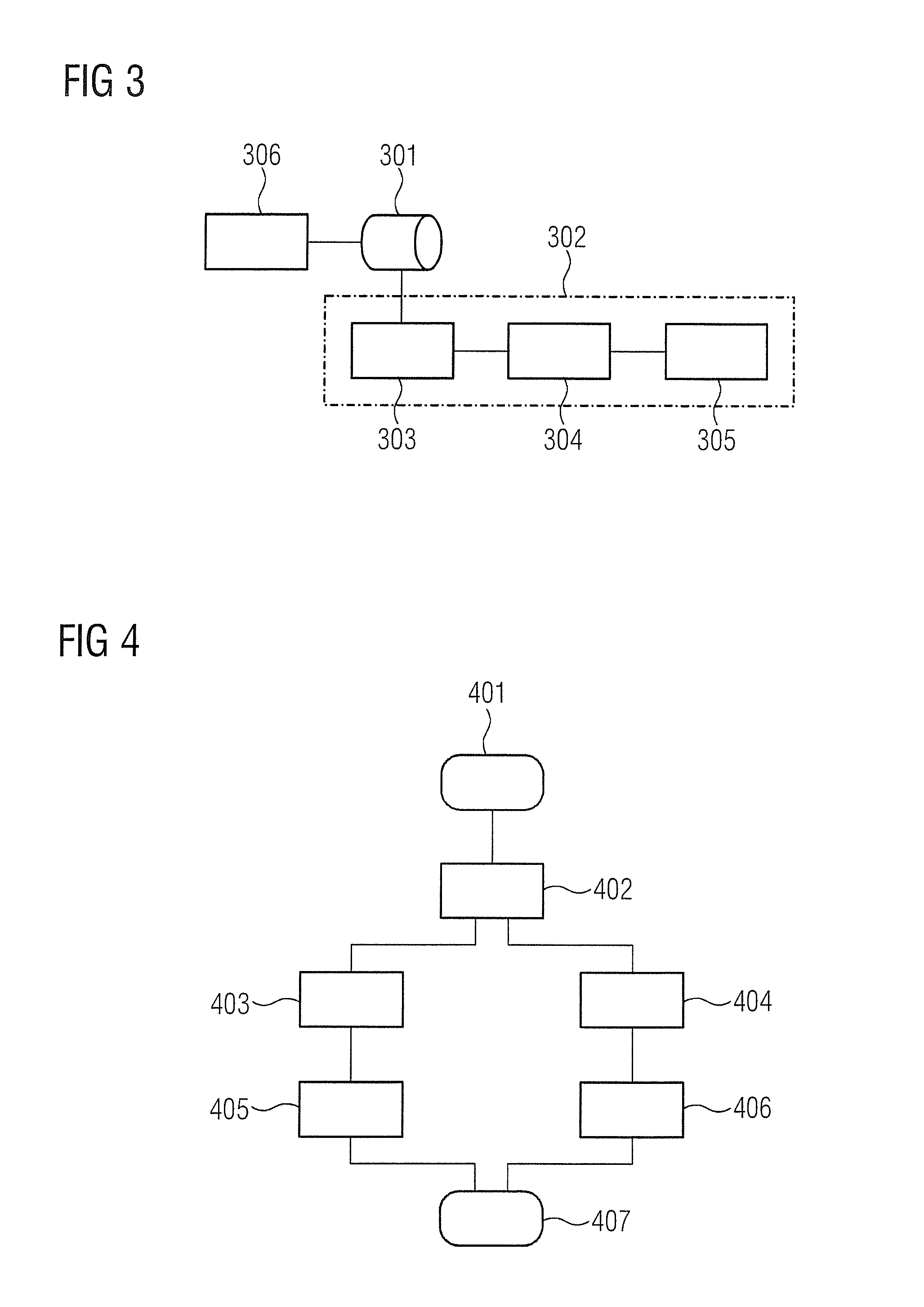
[0112]FIG. 2 shows a curve of an ECG signal having two channels over time in the case of breath-holding of an examination object. The ECG signal is shown as the voltage U over time.

[0113]It can be seen that the curve of the ECG signal in FIG. 2 differs markedly from that in FIG. 1. The amplitude of the R-wave of ECG channel CH1 is increased in FIG. 2 by about 50% compared to the amplitude of the R-wave of ECG channel CH1 in FIG. 1. By contrast, the R-wave of ECG channel CH2 in FIG. 2 can barely still be seen, although the R-wave of ECG channel CH2 in FIG. 1 can be seen very clearly.

[0114]Physiologically this effect may be explained...


PUM


Abstract

In a method for determining R-waves in an ECG signal, at least one reference ECG signal is measured, at least one reference breathing signal is measured, at least one reference R-wave is determined using the reference ECG signal and the reference breathing signal, at least one reference value is determined using the reference ECG signal and the reference breathing signal, at least one comparison rule is credited based on the at least one reference value, ECG signals are measured and breathing signals are measured in which R-waves are to be determined, the measured ECG signals and breathing signals are compared with the at least one reference value using the at least one comparison rule, and at least one R-wave is determined using the measured ECG signals and breathing signals.

Description

BACKGROUND OF THE INVENTION[0001]1. Field of the Invention[0002]The invention concerns a method for determining an R-wave in an ECG signal, as well as an ECG measuring device and a medical imaging device that implement such a method.[0003]2. Description of the Prior Art[0004]ECG measuring devices are primarily used for measuring and monitoring the cardiac function of a patient. For this purpose, the total voltage of the electrical activity of the heart muscle fibers is typically measured as what is known as an “ECG signal” by way of at least two electrodes. Characteristic curves of the ECG signal are identified according to Einthoven by the letters P, Q, R, S and T and conventionally reproduce the different phases of a heartbeat.[0005]There are other applications besides the pure monitoring of the cardiac function of a patient. For example, ECG signals are also used in medical imaging to generate trigger signals. Information about the cardiac phase is obtained via the ECG signal dur...

Claims


Application Information

Patent Timeline
IPC IPC(8): A61B5/352A61B5/08
CPCA61B5/0456A61B5/0816A61B5/04012A61B5/7207A61B5/352
Inventor ROESSLER, JUERGEN
Owner SIEMENS AG
Why Eureka
Eureka Blog
Learn More