
Monitoring system, facility management device, monitoring method, and program

Active Publication Date: 2016-03-17
MITSUBISHI ELECTRIC CORP
View PDF0 Cites 8 Cited by
  • Summary
  • Abstract
  • Description
  • Claims
  • Application Information

AI Technical Summary

Benefits of technology

The present invention notes that it is efficient to notify equipment items of their status and send information regarding them only upon request through a different communication channel. This reduces the amount of data that needs to be sent and improves the overall monitoring of equipment items.

Problems solved by technology

Therefore, it is difficult to directly monitor the states of the equipment items from a PC of a tenant.
Also in such cases, it is difficult to directly monitor the energy usage from a PC of a tenant.
Therefore, the energy management function is not fully utilized.

Method used


Image

  • Monitoring system, facility management device, monitoring method, and program
  • Monitoring system, facility management device, monitoring method, and program
  • Monitoring system, facility management device, monitoring method, and program

Examples


embodiment 1

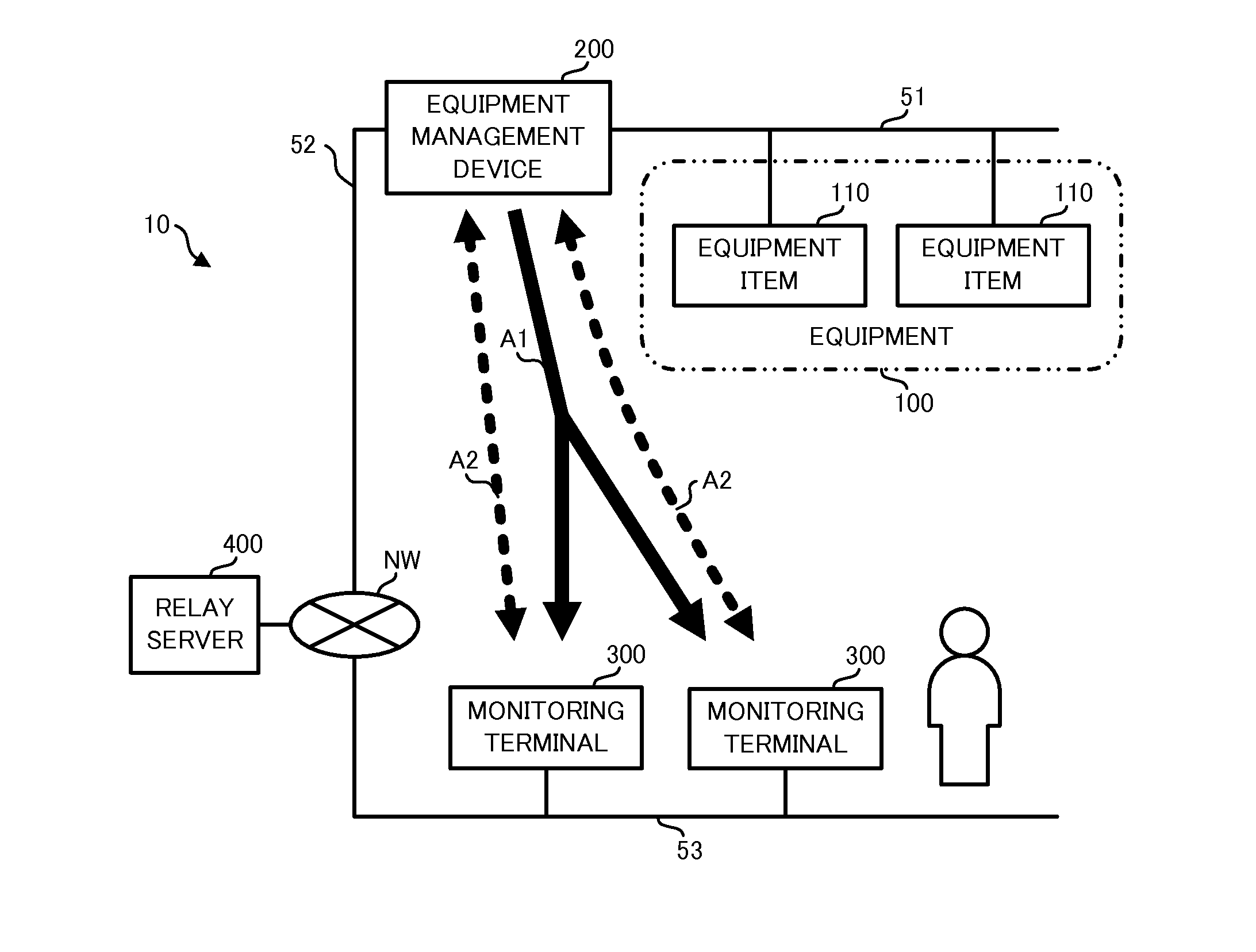
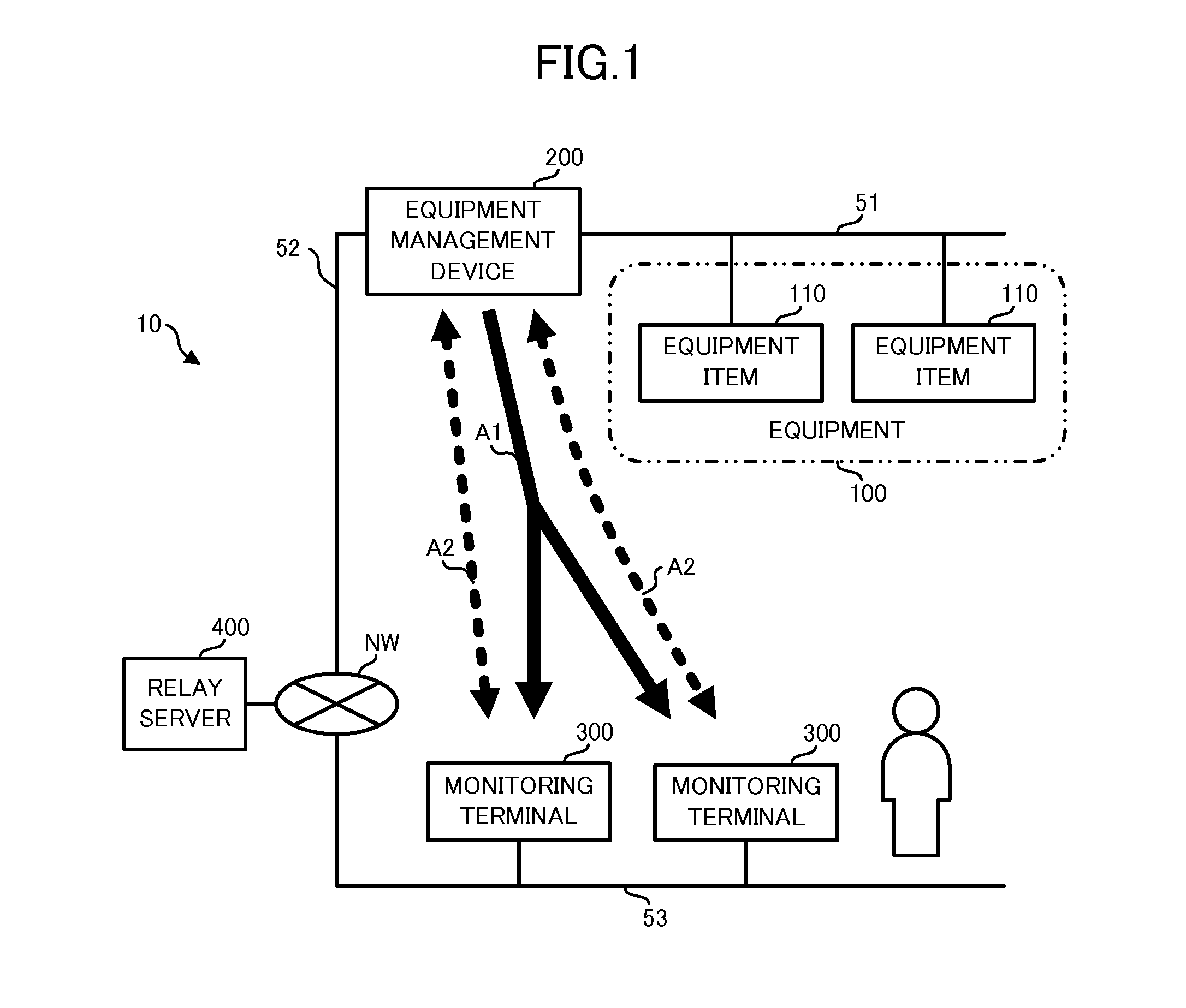
[0027]FIG. 1 shows the configuration of a monitoring system 10 according to this embodiment. The monitoring system 10 is a system for monitoring through a server on a network NW various kinds of information regarding, for example, multiple equipment items 110 installed in an office building. As shown in FIG. 1, the monitoring system 10 has equipment 100 comprising multiple equipment items 110, an equipment management device 200 managing the equipment items 110, multiple monitoring terminals 300 for monitoring information regarding the equipment items 110, and a relay server 400 relaying communication between the equipment management device 200 and monitoring terminals 300.

[0028]The equipment items 110 and equipment management device 200 are mutually communicably connected via a dedicated communication line 51 laid in the office building. Furthermore, the equipment management device 200 is connected to the network NW by a communication line 52 such as an optical fiber so that the equ...

embodiment 2

[0123]Embodiment 2 will be described hereafter mainly in regard to the difference from the above-described Embodiment 1. Here, the same or equivalent components as or to those in the above-described Embodiment 1 are referred to by the equivalent reference numbers and their explanation will be omitted or simplified.

[0124]The monitoring system 10 according to this embodiment is different from the one according to Embodiment 1 in that multiple equipment management devices 200 and 201 are provided as shown in FIG. 10.

[0125]The equipment management device 201 has the same configuration as the equipment management device 200. The equipment management device 201 manages multiple equipment items 610 constituting equipment 600. The equipment 600 comprises equipment items 610 installed on a floor different from the equipment items 110.

[0126]The data manager 420 of the relay server 400 stores, as shown in FIG. 11, connected terminal information 424 presenting the terminals of which the connect...


PUM


Abstract

A monitoring system comprises an equipment management device, a relay server, and monitoring terminals. The equipment management device is configured to establish with the relay server first communication for notifying the monitoring terminals of the states of equipment items. Furthermore, the equipment management device is configured to establish with the relay server second communication, which is different from the first communication, for monitoring equipment information regarding the equipment items from each of the monitoring terminals. The monitoring terminals establish the first communication and second communication with the relay server. The relay server is configured to relay the first communication and second communication.

Description

TECHNICAL FIELD[0001]The present disclosure relates to a monitoring system, equipment management device, monitoring method, and program.BACKGROUND ART[0002]Various kinds of equipment items including air conditioning units and lighting apparatuses are installed in a building such as an office building. Recently, equipment management devices collectively managing such equipment items have emerged. Among such equipment management devices, some devices acquire and notify other devices of the states of the equipment items. Using such an equipment management device, the administrator of the equipment items can monitor the states of the equipment items from, for example, a personal computer (PC) connected via a LAN (local area network) to the equipment management device.[0003]However, the LAN connecting the administrator's PC and the equipment management device is often established as a separate network from the LAN used by tenants of the office building and the like for administrative rea...

Claims


Application Information

Patent Timeline
IPC IPC(8): H04L12/26H04L29/08
CPCH04L67/02H04L43/04H04Q9/00G05B15/02H04L43/045H04L67/75
Inventor ISHIZAKA, TAICHI
Owner MITSUBISHI ELECTRIC CORP
Learn More