Eureka AIR delivers breakthrough ideas for toughest innovation challenges, trusted by R&D personnel around the world.

Dynamic Bleeder Current Control for LED Dimmers

Active Publication Date: 2016-03-17
DIALOG SEMICONDUCTOR
View PDF0 Cites 18 Cited by
  • Summary
  • Abstract
  • Description
  • Claims
  • Application Information

AI Technical Summary

Benefits of technology

The patent describes an LED lamp system that includes a triac dimmer and a bleeder circuit. The bleeper circuit prevents the dimmer from turning off prematurely, and it adjusts the bleecher current based on the AC input voltage to prevent flickering. The technical effect of this invention is to improve the stability and control of LED lamps when using triac dimmers.

Problems solved by technology

However, because LED lamp loads vary widely, triac devices may be unable to operate reliably.
Furthermore, the minimum holding current varies widely among triac devices, which may further complicate the design of LED-based dimmable lighting systems.
As a result, LED lamps may prematurely turn off when they should be on, which may result in a perceivable light flicker or complete failure in the LED lamp.
During the conducting operating mode, a triac dimmer may turn off when the current through the triac dimmer drops below the threshold current level, resulting in a perceivable flicker in the LED lamp.

Method used


Image

  • Dynamic Bleeder Current Control for LED Dimmers
  • Dynamic Bleeder Current Control for LED Dimmers
  • Dynamic Bleeder Current Control for LED Dimmers

Examples


Embodiment Construction

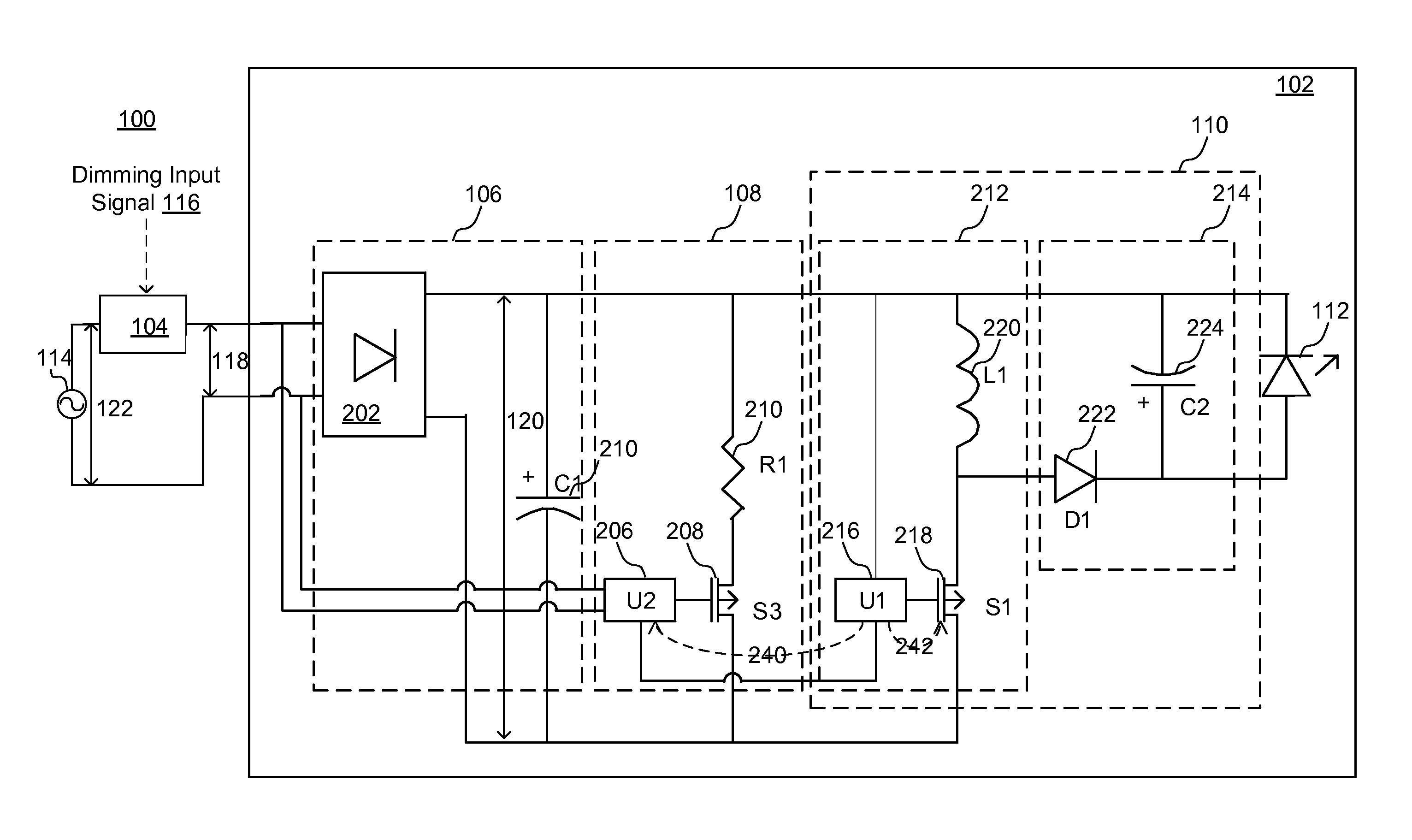
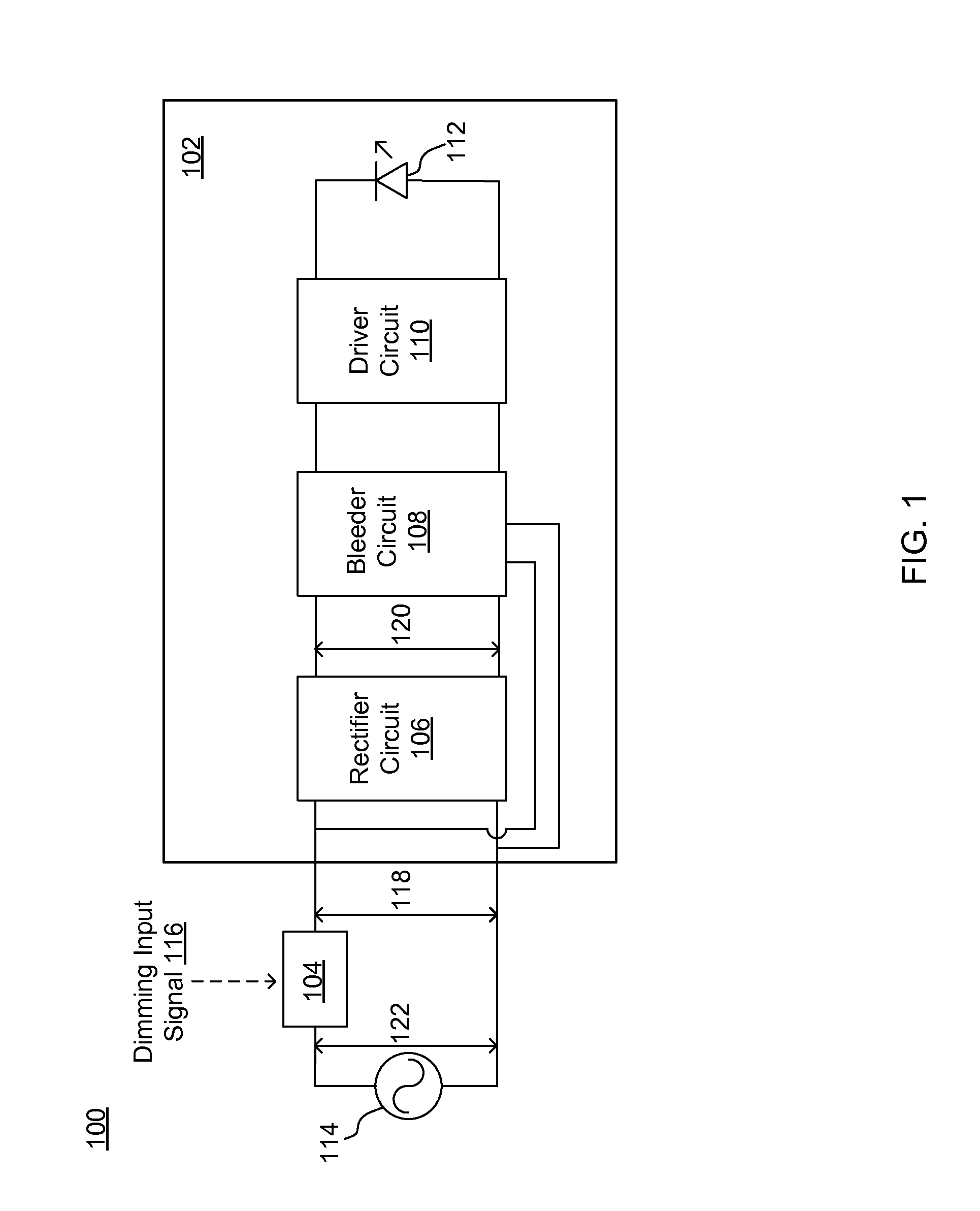
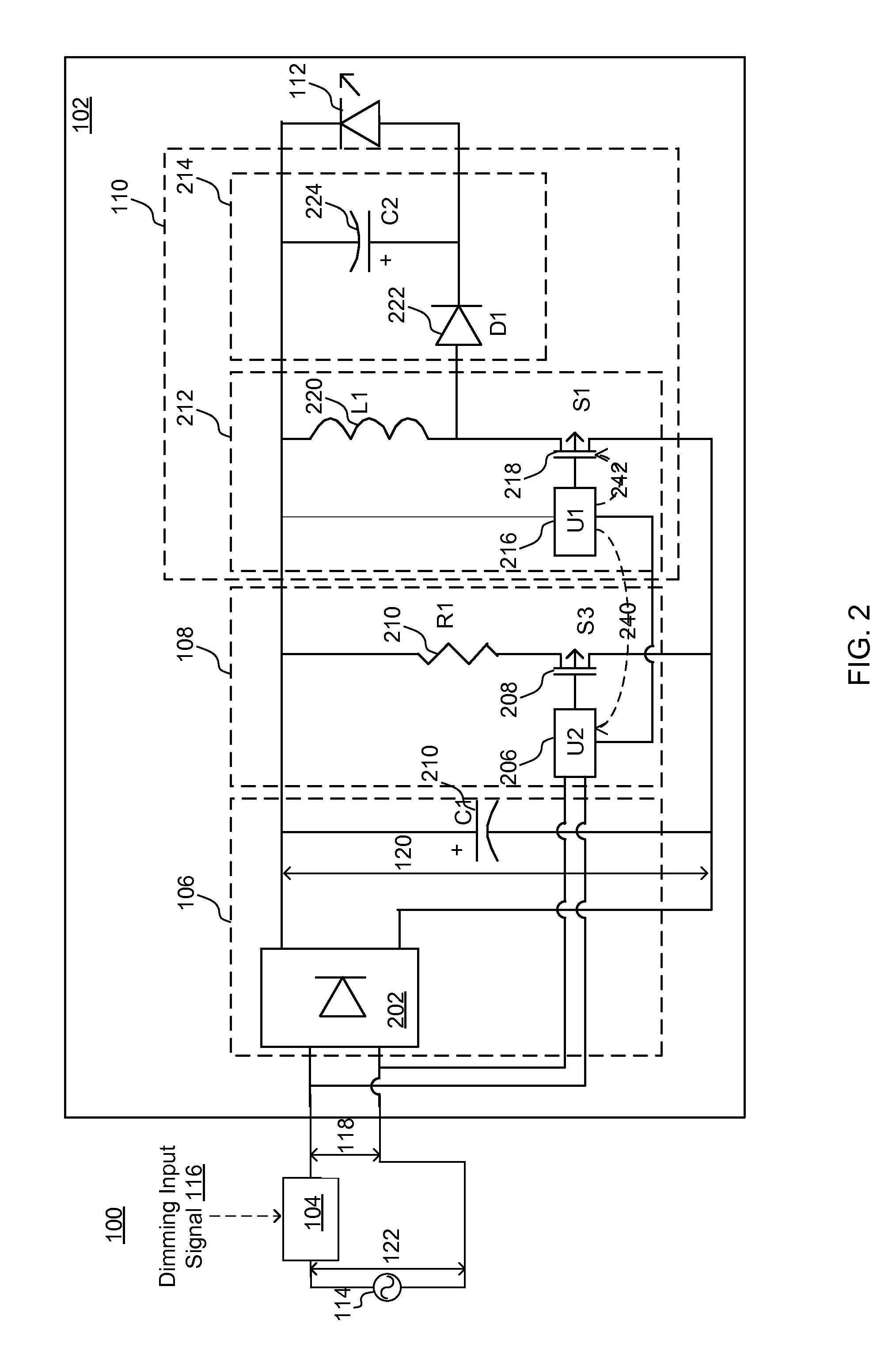
[0018]The Figures (FIG.) and the following description relate to embodiments of the present disclosure by way of illustration only. It should be noted that from the following discussion, alternative embodiments of the structures and methods disclosed herein will be readily recognized as viable alternatives that may be employed without departing from the principles of the present disclosure.

[0019]Reference will now be made in detail to several embodiments of the present disclosure, examples of which are illustrated in the accompanying figures. It is noted that wherever practicable similar or like reference numbers may be used in the figures and may indicate similar or like functionality. The figures depict embodiments of the present disclosure for purposes of illustration only. One skilled in the art will readily recognize from the following description that alternative embodiments of the structures and methods illustrated herein may be employed without departing from the principles ...


PUM


Abstract

LED lamp systems as described herein include a dimmer switch and a bleeder circuit. The bleeder circuit provides a bleeder current to management voltage and to prevent the dimmer switch from turning off prematurely. The bleeder circuit may monitor the AC input voltage outputted by the dimmer switch. When the AC input voltage is less than a first threshold, the bleeder circuit provides a bleeder current. When the AC input voltage is greater than a second threshold, the bleeder circuit adjusts the bleeder current to less than a predetermined level.

Description

CROSS-REFERENCE TO RELATED APPLICATION(S)[0001]This application claims priority under 35 U.S.C. §119(e) to U.S. Provisional Patent Application Ser. No. 62 / 050,704, “Dynamic Bleeder Current Control For LED Dimmer,” filed Sep. 15, 2014, which is incorporated herein by reference in its entirety.BACKGROUND[0002]1. Technical Field[0003]The present disclosure relates to driving LED (Light-Emitting Diode) lamps and, more specifically, to adaptively dimming the LED lamps.[0004]2. Description of the Related Arts[0005]A wide variety of electronics applications now use LED lamps. These applications include architectural lighting, automotive head and tail lights, backlights for liquid crystal display devices, flashlights, and electronic signs. LED lamps have significant advantages compared to conventional lighting sources, such as incandescent lamps and fluorescent lamps. These advantages include high efficiency, good directionality, color stability, high reliability, long life time, small size...

Claims


Application Information

Patent Timeline
IPC IPC(8): H05B44/00
CPCH05B33/0818H05B33/0845H05B33/0887F21V23/003F21V23/04H05B47/10Y02B20/30H05B45/3725H05B45/3575
Inventor WANG, XIAOYANSHI, NANKNOLL, CLARITA CHITINGFENG, GUANG
Owner DIALOG SEMICONDUCTOR
Why Eureka
Eureka Blog
Learn More