Filament cutterhead for a brushcutter

Active Publication Date: 2016-03-24
ANDREAS STIHL AG & CO KG
View PDF0 Cites 17 Cited by
  • Summary
  • Abstract
  • Description
  • Claims
  • Application Information

AI Technical Summary

Benefits of technology

[0005]It is an object of the invention to configure a filament cutterhead for a brushcutter in such a mann

Problems solved by technology

In order to wind a new cutting filament onto a filament spool, a cutting f

Method used


Image

  • Filament cutterhead for a brushcutter
  • Filament cutterhead for a brushcutter
  • Filament cutterhead for a brushcutter

Examples


Embodiment Construction

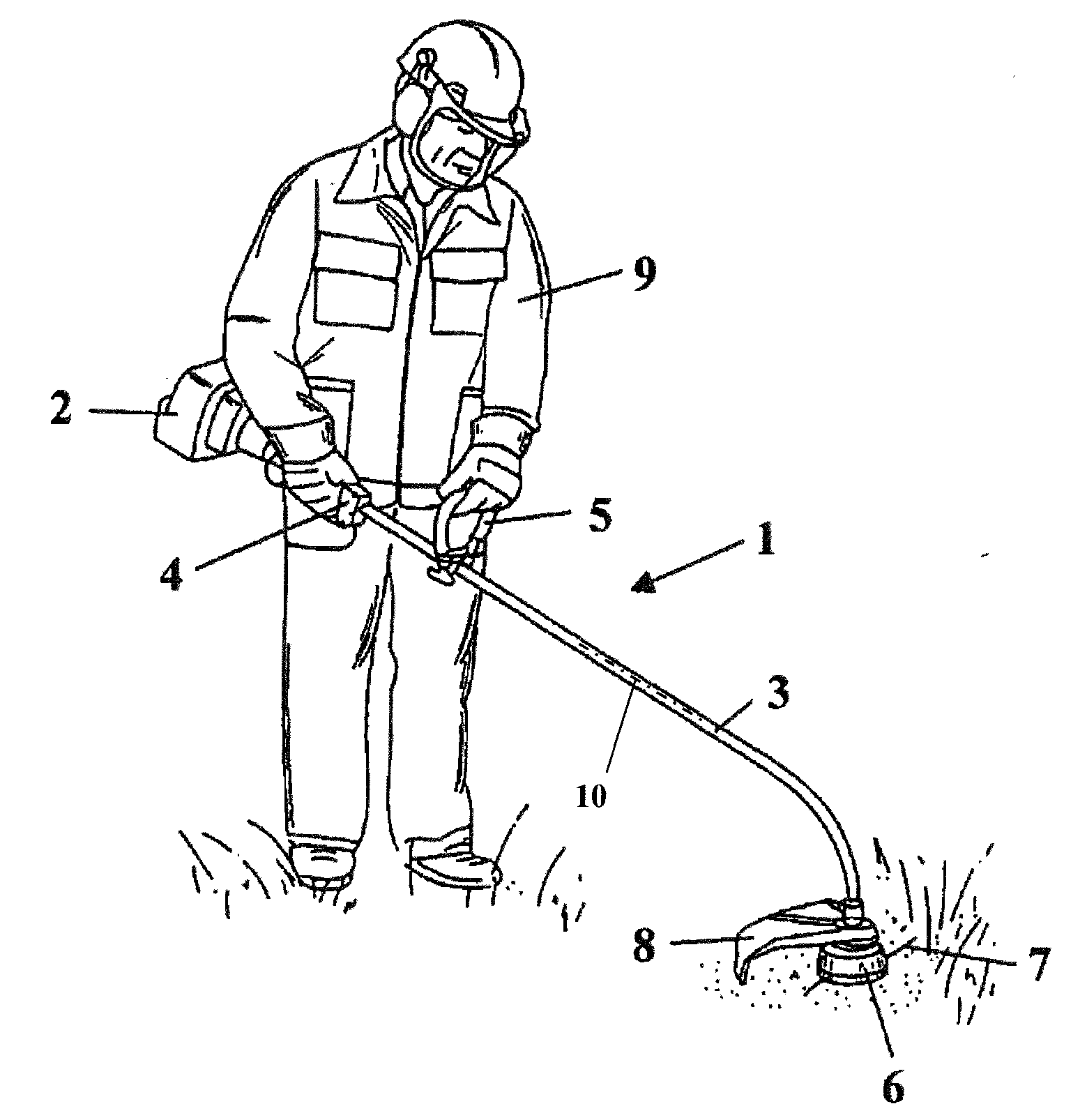
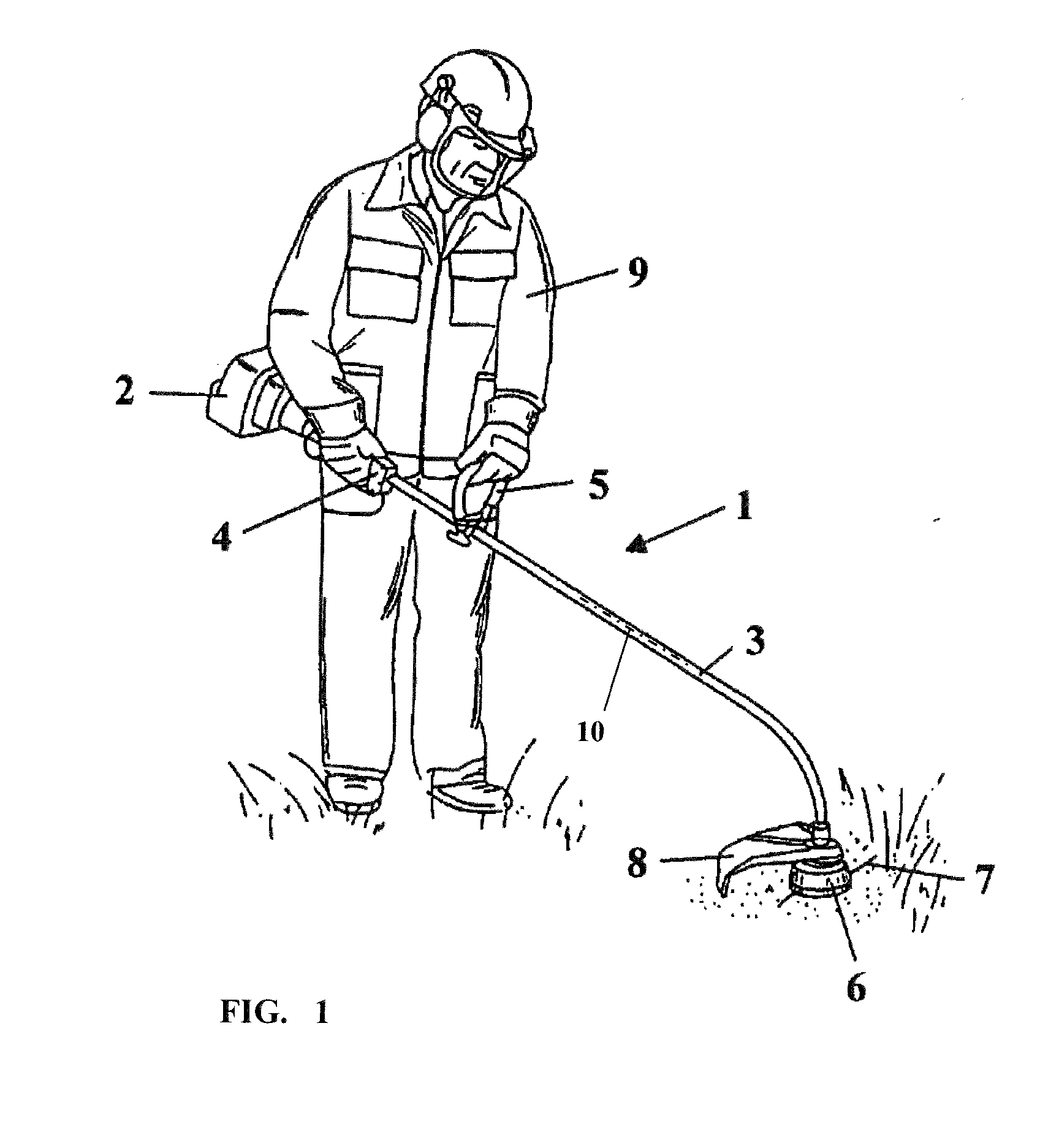
[0042]FIG. 1 shows, by way of example, a brushcutter 1 which essentially comprises a guide tube 3, at the one end of which a drive motor 2 and at the other end of which a filament cutterhead 6 are mounted. The brushcutter has a first handle 4 with operating elements for the drive motor 2; a bale handle 5 is mounted between the handle 4 and the filament cutterhead 6 such that a user 9 can carry and guide the brushcutter via the handle 4 and the bale handle 5. The filament cutterhead 6 is connected to the drive motor 2 via a drive shaft 10. If a curved guide tube 3 is used—as shown in the embodiment—the drive shaft is a flexible drive shaft; alternatively, the guide tube can be a rectilinear guide tube, and therefore the drive shaft 10 can be configured as a rigid shaft.

[0043]The filament cutterhead 6 is mounted on the drive shaft 10 and is driven in a rotating manner by the latter. The ends of a cutting filament 7, which serves as cutting tool, protrude from the housing of the filame...


PUM


Abstract

A filament cutterhead is provided for mounting on the drive shaft of a brushcutter. The filament cutterhead includes a housing with a circumferential wall wherein a first wall opening for a cutting filament is formed. A filament spool arranged in the housing is rotatable relative to the housing. A filament channel with a filament inlet segment is provided in a partition wall of the filament spool. The filament channel extends from the filament inlet segment past the hub to a filament outlet segment which is assigned a second wall opening in the circumferential wall. The filament outlet segment is at an offset (v) with respect to the filament inlet segment in the circumferential direction of the hub. The mouth of the filament inlet segment and the mouth of the filament outlet segment lie within an outside diameter (A) of the partition wall and open into a pass-through space.

Description

CROSS REFERENCE TO RELATED APPLICATION[0001]This application claims priority of German patent application no. 10 2014 019 548.1, filed Dec. 23, 2014, the entire content of which is incorporated herein by reference.BACKGROUND OF THE INVENTION[0002]U.S. Pat. No. 6,263,580 discloses a filament cutterhead with a filament spool, in which, in a predetermined rotational position, a cutting filament can be inserted through a wall opening in the circumferential wall of the housing and can be coiled up by manual rotation of the filament spool. The cup-shaped housing has a first wall opening and a second wall opening in the circumferential wall for each cutting filament to be wound up. The filament spool has a hub on which a disk-shaped partition wall is arranged. The partition wall divides the filament spool into a first upper winding section and a second lower winding section, wherein a filament-guiding filament channel is formed in the partition wall, into which the cutting filament to be c...

Claims


Application Information

Patent Timeline
IPC IPC(8): A01D34/416
CPCA01D34/4165A01D34/4166
Inventor LANG, SVENRETHABER, ACHIM
Owner ANDREAS STIHL AG & CO KG
Why Eureka
Try Eureka