Fluid mixing structure

a technology of mixing structure and flue gas, which is applied in the field of respiratory therapy, can solve the problems of difficulty in effective respiration, less effective gas therapy than desired, and patient dealing with respiratory illness

Active Publication Date: 2016-03-24
FISHER & PAYKEL HEALTHCARE LTD
View PDF6 Cites 40 Cited by
  • Summary
  • Abstract
  • Description
  • Claims
  • Application Information

AI Technical Summary

Benefits of technology

[0008]Certain features, aspects and advantages of at least one of the configurations disclosed herein include the realization that a respiratory therapy system may comprise a static mixer adapted to mix a pair of gases upstream of a gas composition sensing region. The static mixer may receive gas flows that are at least partially spaced apart and mix the gas flows. For example, the static mixer may receive gas flows that are at least in part vertically and / or horizontally spaced apart and mix the gas flows in a vertical and / or horizontal direction. The mixing may improve the accuracy of a gas composition sensor used in the gas composition sensing region.
[0041]In use, the pinch can accelerate a flow of gases passing through the static flow mixer. In use, gases passing through the static flow mixer can swirl and expand after passing the first baffle and through the pinch. In use, gases passing through the static flow mixer can swirl and expand after passing the second baffle and through the second pinch. The first and baffles can each extend past a central horizontal plane of the static flow mixer such that the first and second baffles provide a tortuous path for a flow of gases through the static flow mixer.

Problems solved by technology

A patient dealing with respiratory illness, for example chronic obstructive pulmonary disease (COPD), can have difficulty engaging in effective respiration.
This difficulty may be the result of a variety of physiological faults, including a breakdown of lung tissue, dysfunctions of the small airways, excessive accumulation of sputum, infection, genetic disorders, or cardiac insufficiency.
If the ratio of oxygen to air is too high or, vice versa, if the ratio of air to oxygen is too high, the gas therapy may be less effective than desired.
It has been discovered that, in some cases, the accuracy of sensors used to measure the concentration of one or more gases passing through or along a gas passageway of a respiratory therapy system may be lower than desired, particularly if the gases fed to the sensor are not properly mixed.
If, when using such a sensing arrangement, the gases composition in a given cross-section is such that the oxygen gas is substantially located in the plane of measurement and the air is substantially located outside of the plane of measurement, the true composition of the gases can be difficult to determine.

Method used


Image

  • Fluid mixing structure
  • Fluid mixing structure
  • Fluid mixing structure

Examples


Embodiment Construction

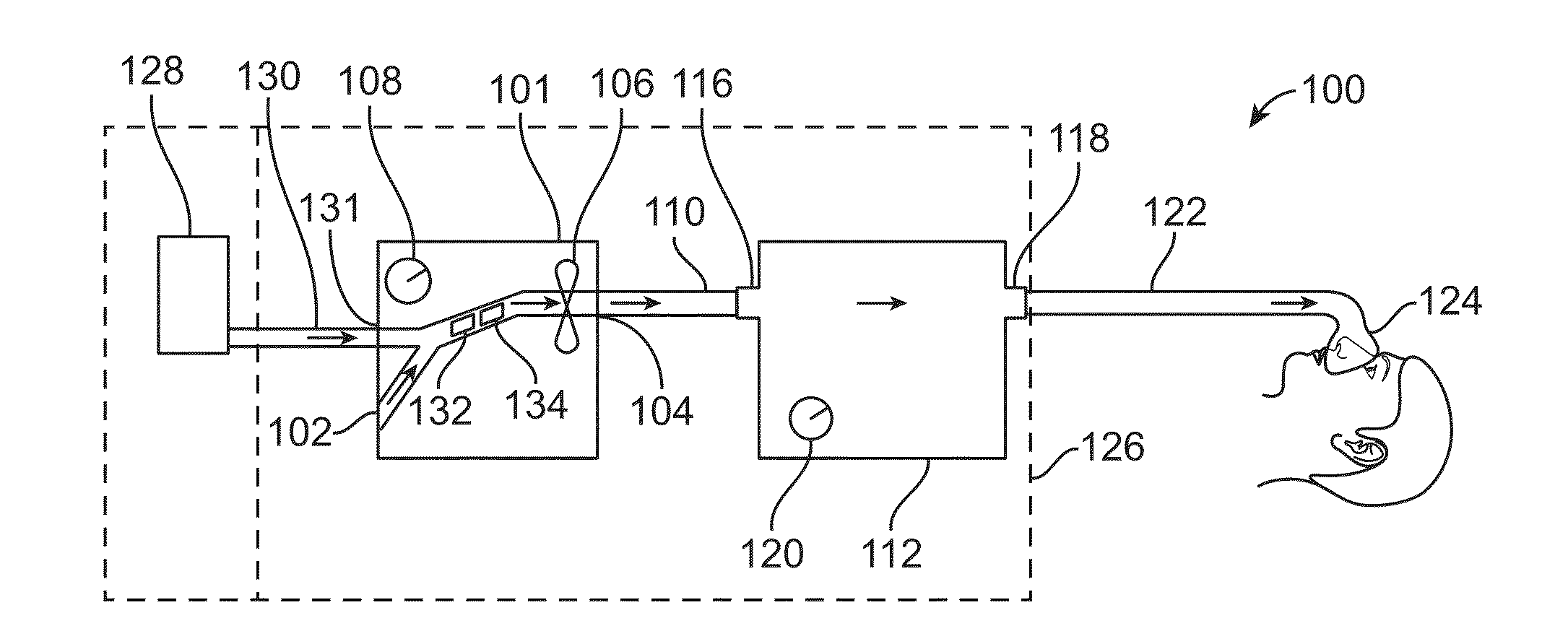
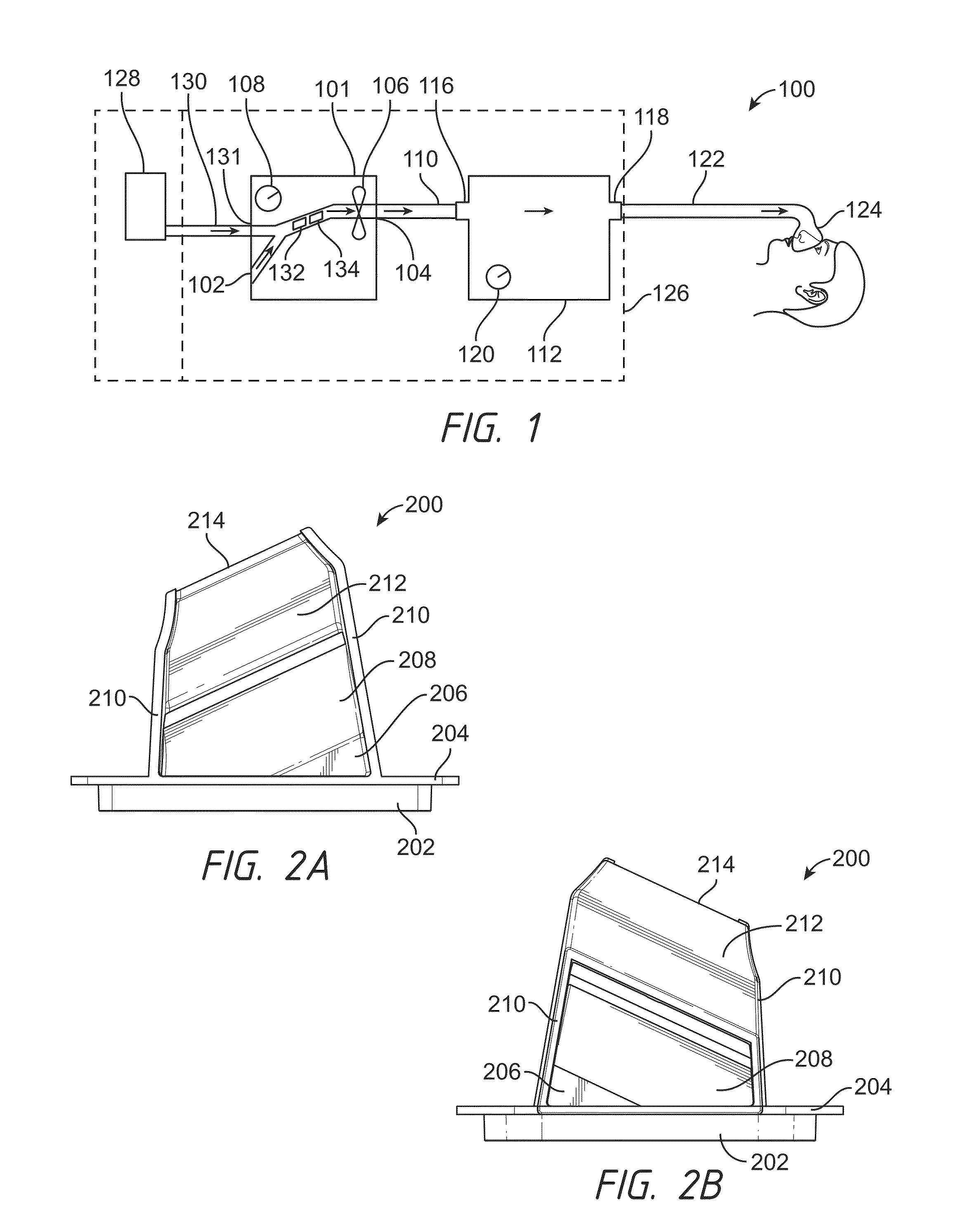
[0069]With reference to FIG. 1, a configuration for a respiratory therapy system 100 is shown. In the illustrated configuration, the respiratory therapy system 100 may comprise a flow generator 101. The flow generator 101 may comprise a first gas inlet 102 and a gas outlet 104. The flow generator 101 may comprise a blower 106. The blower 106 may comprise a motor. The motor may comprise a stator and a rotor. The rotor may comprise a shaft. An impeller may be linked to the shaft. In use, the impeller may rotate concurrently with the shaft to draw in gas from the first gas inlet 102. The flow generator 101 may comprise a user interface 108 which may comprise one or more buttons, knobs, dials, switches, levers, touch screens, speakers, displays, and / or other input or output modules so that a user might use to input commands into the flow generator 101 to view data and / or control its operation and / or the operation of other aspects of the respiratory therapy system 100. The flow generator...


PUM

PropertyMeasurementUnit
angleaaaaaaaaaa
angleaaaaaaaaaa
angleaaaaaaaaaa

Abstract

A respiratory therapy system can have a flow generator adapted to provide gases to a patient. A gas passageway can be located in-line with the flow generator. The gas passageway can have a first portion adapted to receive a first gas and a second portion adapted to receive a second gas. The gas passageway can have a static mixer downstream of the first and second portions.

Description

CROSS-REFERENCE TO RELATED APPLICATIONS[0001]The present application claims the priority benefit of U.S. Provisional Application No. 62 / 026,804, filed Jul. 21, 2014, the entirety of which is hereby incorporated by reference herein.BACKGROUND[0002]1. Technical Field[0003]The present disclosure generally relates to respiratory therapy. More particularly, the present disclosure relates to structures for mixing gases used in respiratory therapy systems.[0004]2. Description of the Related Art[0005]A patient dealing with respiratory illness, for example chronic obstructive pulmonary disease (COPD), can have difficulty engaging in effective respiration. This difficulty may be the result of a variety of physiological faults, including a breakdown of lung tissue, dysfunctions of the small airways, excessive accumulation of sputum, infection, genetic disorders, or cardiac insufficiency. With some respiratory illnesses, it is useful to provide the patient with a therapy that can improve the ve...

Claims


Application Information

Patent Timeline
Patent Type & Authority Applications(United States)
IPC IPC(8): A61M16/12A61M16/00A61M16/10B01F23/10
CPCA61M16/125B01F5/0602B01F3/026A61M16/0057A61M2016/003A61M16/1005A61M16/105A61M2205/3375A61M2205/3368A61M16/0003A61M16/0066A61M16/12A61M16/16A61M2016/0027A61M2016/102A61M2016/1025A61M2016/103A61M2202/0208A61M2206/11A61M2206/14A61M2230/04A61M2230/10A61M2230/201A61M2230/202A61M2230/205A61M16/109A61M16/1095A61M16/161A61M16/024B01F23/10B01F25/4231B01F35/213B01F35/2202B01F35/2211
Inventor BARKER, DEAN, ANTONYBURGESS, RUSSEL, WILLIAMHAWKINS, PETER, GEOFFREYCHAI, MAURICE, WEN-BIN
Owner FISHER & PAYKEL HEALTHCARE LTD
Why Eureka
Try Eureka