System for Forming Stacks of Composite Materials

Active Publication Date: 2016-03-24
APPLUS SERVICIOS TECHCOS
View PDF5 Cites 6 Cited by
  • Summary
  • Abstract
  • Description
  • Claims
  • Application Information

AI Technical Summary

Benefits of technology

[0027]It allows forming laminates of variable thickness and composition. Thus, laminates can be formed of variable section and no-straight geometry.
[0028]It allows that the threading of the laminate inside the nozzle can be performed automatically, because the nozzle and the initial part of the laminate can be formed simultaneously. That is, the laminate can be flat between the two transition elements at the time of forming the nozzle with the form and the final co

Problems solved by technology

Although this apparatus allows manufacturing straight structural sections with changes in thickness and bends, it is not capable of manufacturing more complex geometries, such as for example geometries with changes in plane for overcoming obstacles (joggles), twisted geometries, etc.
Furthermore, even for obtaining simple geometric shapes, such as for example components with an omega-shaped cross-section, it is necessary to have

Method used


Image

  • System for Forming Stacks of Composite Materials
  • System for Forming Stacks of Composite Materials
  • System for Forming Stacks of Composite Materials

Examples


first embodiment

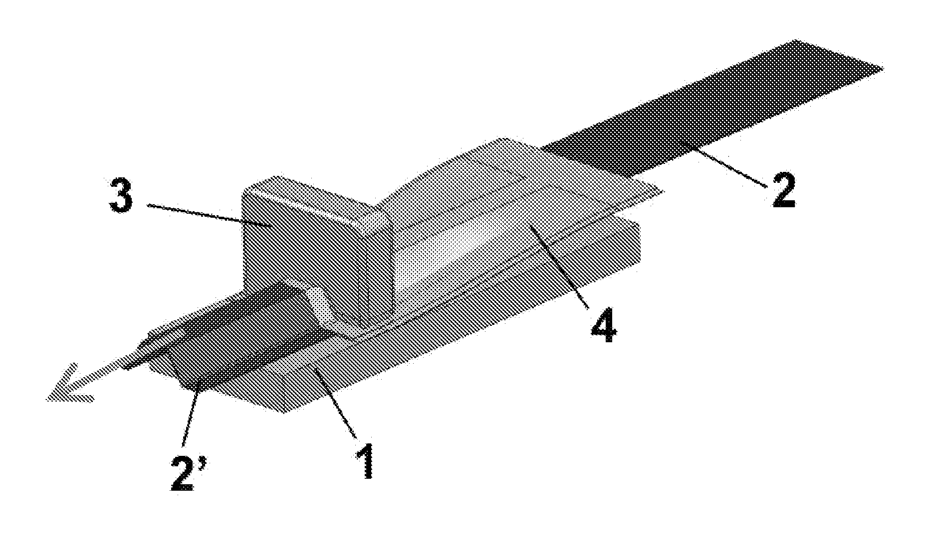
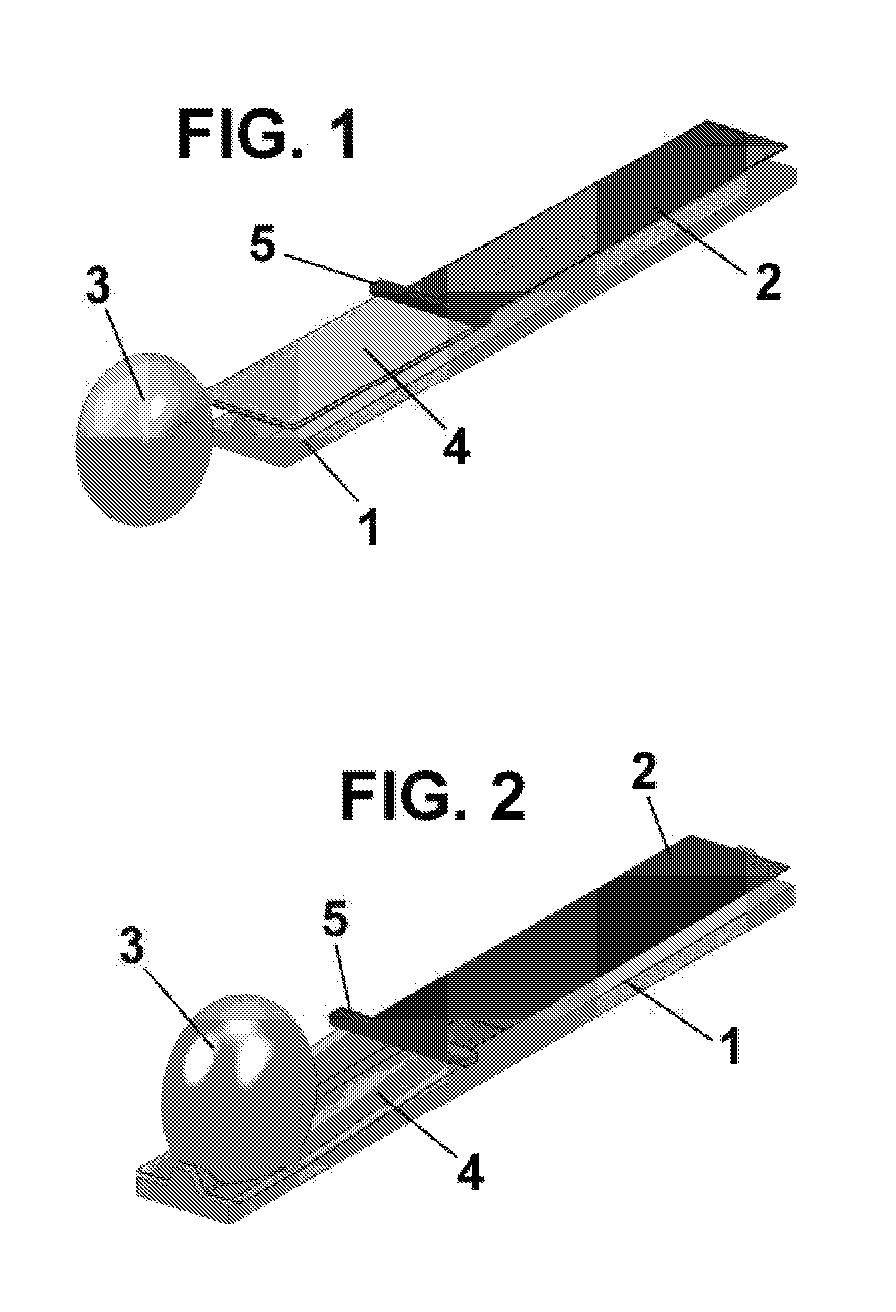
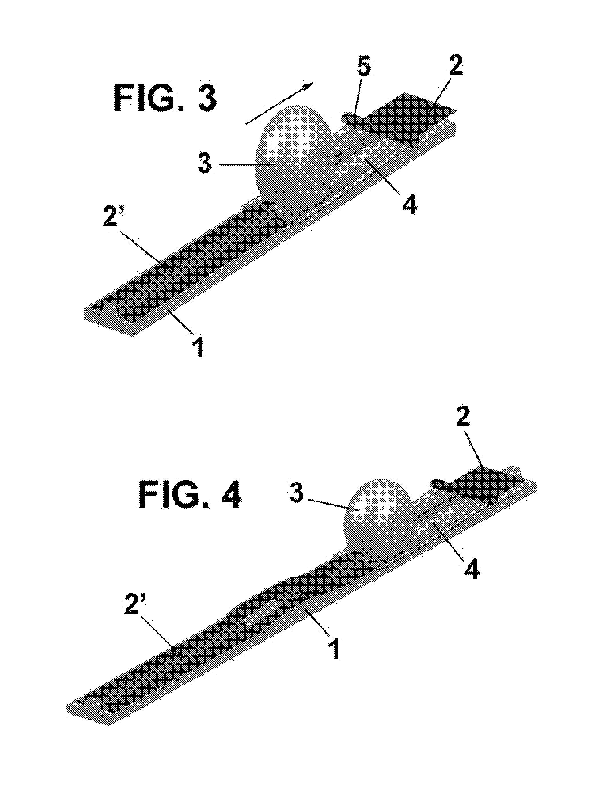
[0038]FIGS. 1 to 3 are perspective views of the system for forming stacks of composite materials of the present invention as a first embodiment, which represent the stages of forming a stack;

[0039]FIG. 4 is a perspective view of a variant of the system for forming stacks of composite materials of the present invention, as an alternative of said first embodiment;

second embodiment

[0040]FIGS. 5 to 7 are perspective views of the system for forming stacks of composite materials of the present invention which represent the stages of forming a stack;

[0041]FIG. 8 is a perspective view of a variant of the system for forming stacks of composite materials of the present invention, according to an alternative of said second embodiment;

third embodiment

[0042]FIGS. 9 to 12 are perspective views of the system for forming stacks of composite materials of the present invention, which represent the stages of forming a stack.

DESCRIPTION OF PREFERRED EMBODIMENTS OF THE INVENTION

[0043]In FIGS. 1 to 3 is shown a first embodiment of the system for forming stacks of composite materials according to a first embodiment.

[0044]According to this first embodiment, the system of the present invention comprises a form 1, for example an elongated mandrel 1. This form 1 has a complex geometry, for example a Ω-shaped, that is the one that wants to be provided to a stack 2 of composite material, which is placed on said form 1 (right side of FIGS. 1 to 3).

[0045]The system of the present invention also comprises the transition elements 4, which can provide heat. The function of these transition elements 4 is to define a nozzle flexible and adaptable to different geometries.

[0046]In the case of providing heat, they also have the function of heating the st...


PUM

PropertyMeasurementUnit
Lengthaaaaaaaaaa
Flexibilityaaaaaaaaaa

Abstract

The system for forming stacks of composite materials comprises a form (1) which defines the section that is desired to provide to a stack (2) of composite material placed thereon to obtain a formed stack (2′); a counter-form (3), which together with the form (1), forms and obtains the formed stack (2′); and it is characterized in that the system also comprises transition elements (4) deformable, that adopt a variable section from an initial section in one of its ends and the end section defined by the form (1) in the other end.
It allows changing the geometry during the forming of the laminate, to obtain laminates of variable section along its length. For this purpose, the form and counter-form must have a variable geometry at will.

Description

OBJECT OF THE INVENTION[0001]The present invention refers to a system for forming stacks of composite materials; where which said system has application in the technical field of systems for forming stacks of prepreg composite materials, particularly in the area of systems for continuous production of profiles of these stacks.[0002]This system aims to automate the process of forming stacks of composite materials, formed from different physical entities and stages, where the number of entities and stages are highly flexible to form complex geometries of these stacks of composite materials.BACKGROUND OF THE INVENTION[0003]As an introduction, it is known that the pieces obtained from stacked composite materials, such as those formed of carbon fiber sheets or glass fibers pre-impregnated with resin (“prepreg”), are widely employed in industry, such as in the aeronautics industry components including stringers, stiffeners and structural reinforcements. These components are characterized ...

Claims


Application Information

Patent Timeline
IPC IPC(8): B29C70/50B29C53/04
CPCB29C70/504B29C53/04B29L2007/008B29L2009/00B29K2101/00B29C70/386B29C70/541B30B5/02
Inventor BRUFAU, REDONDO, JORDI
Owner APPLUS SERVICIOS TECHCOS
Why Eureka
Try Eureka