Methods and systems for tracking and guiding sensors and instruments

a technology for tracking and guiding sensors and instruments, applied in the field of position and orientation determination devices, can solve the problems of inability to track, limited spatial resolution, expensive, inconvenient, etc., and achieve the effect of reducing ultrasound artifacts and speckles, and improving the quality of tissue types and elastomeric properties

Active Publication Date: 2016-08-25
ZITEO INC
View PDF0 Cites 35 Cited by
  • Summary
  • Abstract
  • Description
  • Claims
  • Application Information

AI Technical Summary

Benefits of technology

[0237]Another field where aspects of this invention can provide significant advantages is in environmental surveys. Spatial registration systems attached to surveying sensors can be used to automatically perform environmental surveys. The spatial registration system will conveniently provide the position and orientation of the system in relationship to the investigated objects or to the adjacent environmental objects, keeping an automatic log of the surveyed locations. This capability will also allow for an automatic mapping of the investigated features.

Problems solved by technology

Yet, the flexibility and adaptability of hand-held sensors also can make them difficult to track.
Prior art approaches at spatial registration of sensors and instruments are bulky, cumbersome, expensive, or not practical.
Unfortunately, GPS only provides coarse, limited spatial resolution and does not work reliably when satellite GPS signals are weak.
This position resolution is too coarse for many applications, including medical diagnostic and medical interventions where multiple electronic instruments and metallic objects are used.
Generally, CMM camera systems are bulky, expensive and impractical for most applications in where hand-held systems are used or desirable.
One drawback of this approach is that a continuous line of sight needs to exist between external cameras placed above a surgery table and all of the markers placed on probes, instruments, and samples.
The hands, arms, and heads of the surgeons may easily break the line of sight during surgery procedures.

Method used


Image

  • Methods and systems for tracking and guiding sensors and instruments
  • Methods and systems for tracking and guiding sensors and instruments
  • Methods and systems for tracking and guiding sensors and instruments

Examples


Embodiment Construction

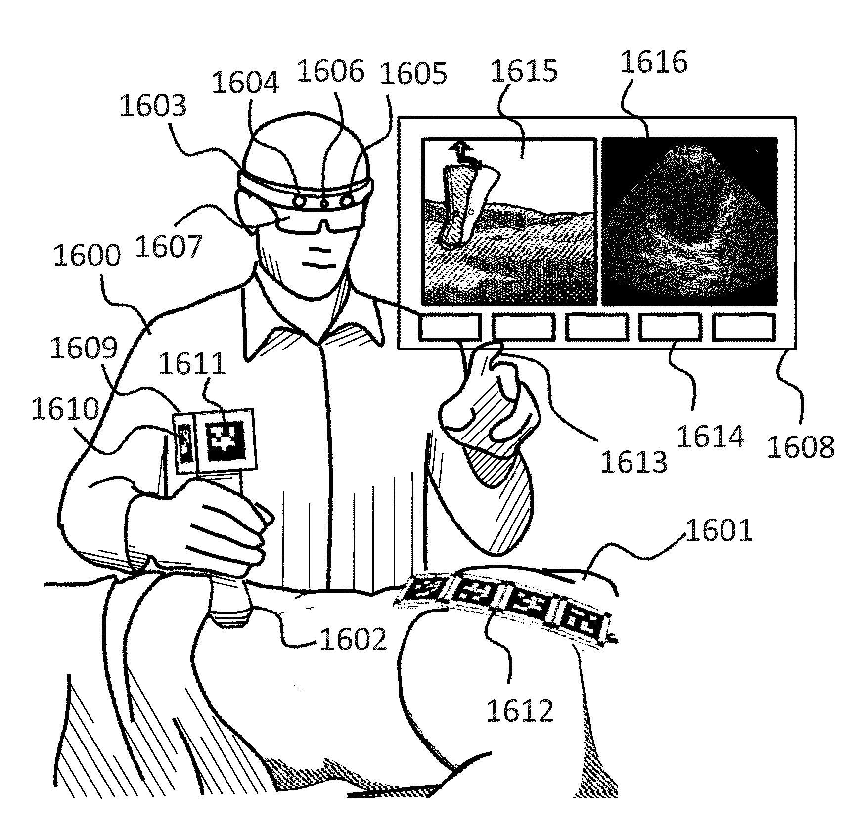
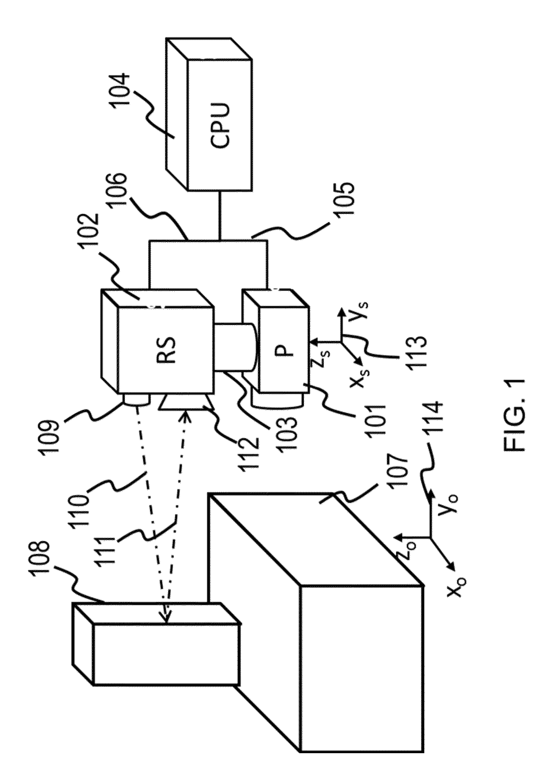
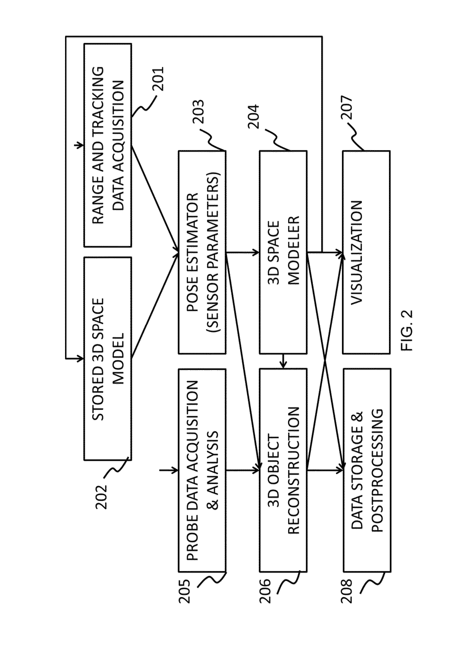
[0062]Herein are described methods and systems using these methods aimed at providing position and orientation (or spatial registration) for various instruments, such as hand-held probes, sensors, scanners, imagers or other instruments, with respect to investigated objects and environmental objects. An instrument can generically be referred to as a “probe.”

[0063]The purpose of spatial registration can be multiple-fold. One benefit is the introduction of the capability to provide three dimensional (3D) models of the investigated objects. These 3D models can include multiple layers of information, such as physical characteristics, as well as other characteristics provided by probe. Another benefit is the determination of the position and orientation of the probe in relationship to the investigated environment. As a result of this, a three dimensional distribution of the quantity measured by the probe can be determined. One dimensional (1D) or two dimensional (2D) distributions can als...


PUM


Abstract

A shared-housing ultrasound transducer and machine-vision camera system is disclosed for registering the transducer's x, y, z position in space and pitch, yaw, and roll orientation with respect to an object, such as a patient's body. The position and orientation are correlated with transducer scan data, and scans of the same region of the object are compared in order to reduce ultrasound artifacts and speckles. The system can be extended to interoperative gamma probes or other non-contact sensor probes and medical instruments. Methods are disclosed for computer or remote guiding of a sensor probe or instrument with respect to saved positions and orientations of the sensor probe.

Description

CROSS-REFERENCES TO RELATED APPLICATIONS[0001]This application is a divisional of U.S. application Ser. No. 13 / 789,143, filed Mar. 7, 2013, which claims the benefit of U.S. Provisional Application No. 61 / 699,750, filed Sep. 11, 2012, and U.S. Provisional Application No. 61 / 607,676, filed Mar. 7, 2012, all of which are hereby incorporated by reference in their entireties for all purposes.STATEMENT AS TO RIGHTS TO INVENTIONS MADE UNDER FEDERALLY SPONSORED RESEARCH AND DEVELOPMENT[0002]Not ApplicableBACKGROUND[0003]1. Field of the Invention[0004]Generally, this application relates to position and orientation determination devices for surgery and other contexts. Specifically, this application relates to computer vision and ranging tracking systems for medical instruments and sensor probes.[0005]2. Background[0006]Currently, hand-held sensor systems are being used for several applications, ranging from environmental surveys of chemical, biological and radioactive environments, to medical...

Claims


Application Information

Patent Timeline
Patent Type & Authority Applications(United States)
IPC IPC(8): A61B8/08A61B34/20A61B90/00A61M37/00
CPCA61B5/064A61M37/0069A61B5/0077A61B8/13A61B8/4254A61B8/483A61B8/4444A61B8/462A61B8/463A61B8/485A61B8/5253A61B8/5269A61B8/4245A61B8/4438G01S15/8936G01S17/89G01S7/52065G01S7/52077G01S7/52079G01S15/899G01S15/8993G01S17/023G01S17/66A61B8/4427A61B8/5238A61B34/20A61B90/361A61B2090/363A61B8/5261A61B5/065A61B6/4258A61B6/4417A61B6/4405G01S17/86G01S17/894
Inventor MIHAILESCU, LUCIANNEGUT, VICTOR ARIE
Owner ZITEO INC
Why Eureka
Try Eureka