Auto-retracting mechanism for faucet spray head

a technology of spray head and auto-retracting mechanism, which is applied in the direction of water installation, construction, domestic plumbing, etc., can solve the problems of mechanism not being optimal, spray head may not fully retract to its docking position,

Active Publication Date: 2016-03-24
AS AMERICA
View PDF6 Cites 7 Cited by
  • Summary
  • Abstract
  • Description
  • Claims
  • Application Information

AI Technical Summary

Benefits of technology

[0004]Generally speaking, it is an object of the present invention to provide an auto-retracting mechanism for a faucet spray head that avoids disadvantages of prior art constructions.
[0006]It will be appreciated that the inventive auto-retracting mechanism can be provided as a module that can be easily installed in the faucet spout tube without requiring additional machining of the tube, and the adapter can be screwed into or otherwise secured to the spray head.
[0007]In some embodiments, a docking assembly configured to attach to a faucet body is provided. The docking assembly can include a shell and a gripping member slidably housed at least partially within the shell. The gripping member can include a gripper body and a gripper ring extending from the gripper body. The docking assembly may further include a turret fixed within the shell and concentrically arranged about at least a portion of the gripping member. The turret can include a first end having a chamfered interior wall for interacting with a docking assembly engagement member of a spray head adapter. The docking assembly can also include a captive spring arranged between the gripper ring and a second end of the turret. The captive spring can provide a motive force to slide the gripping member from an extended position to a docked position.
[0008]In some embodiments, the docking assembly can also include latching jaws pivotably arranged between the turret and the shell. The latching jaws can latch onto the gripper ring when the docking assembly is in the extended position and pivot to de-latch from the gripper ring when the docking assembly is moved from the extended position to the docked position. Each latching jaw can additionally include an adapter engagement member for receiving the docking assembly engagement member of the adapter between the adapter engagement member and the shell. Interaction between the docking assembly engagement member and the adapter engagement member pivots the latching jaws to disengage them from the gripper ring, which allows the captive spring to bear against the gripper ring, thereby moving the docking assembly into the docked position. In some embodiments, a compression ring may be retained within bores formed in the adapter engagement members to provide a radially outward directed force upon the adapter engagement members, which can serve to retain the docking assembly in the extended position until the docking assembly engagement member interacts with the adapter engagement member and overcomes the radially outwardly directed force provided by the compression ring.
[0010]In some embodiments, the gripping member can include flanged fingers that extend away from the gripper body and include a flange directed at least partially radially inward. When the flanged fingers are under no load, they may extend at least partially beyond an outer dimension of the gripper body. The flanged fingers can slide along the chamfered interior wall of the turret as the docking assembly is moved from the extended position to the docked position. As the gripping member slides, the chamfered interior wall provides an increasing load upon the flanged fingers thereby providing a radially inwardly directed force upon the flanged fingers.
[0013]In some embodiments, the gripping member grips the latching rib as the auto-retracting mechanism is moved from the extended position to the docked position to pull the adapter into engagement with the docking assembly. A latching O-ring arranged in a circumferential depression adjacent to the latching rib may also be provided to increase the friction between the gripping member and the latching rib.

Problems solved by technology

With such constructions, the spray heads may not fully retract to their docking positions due to hose friction and / or alignment issues between the spray heads and the spout tubes.
Detents or magnets can be employed to assist in docking the spray heads to the faucet bodies; however, such mechanisms may not be optimal.

Method used


Image

  • Auto-retracting mechanism for faucet spray head
  • Auto-retracting mechanism for faucet spray head
  • Auto-retracting mechanism for faucet spray head

Examples


Embodiment Construction

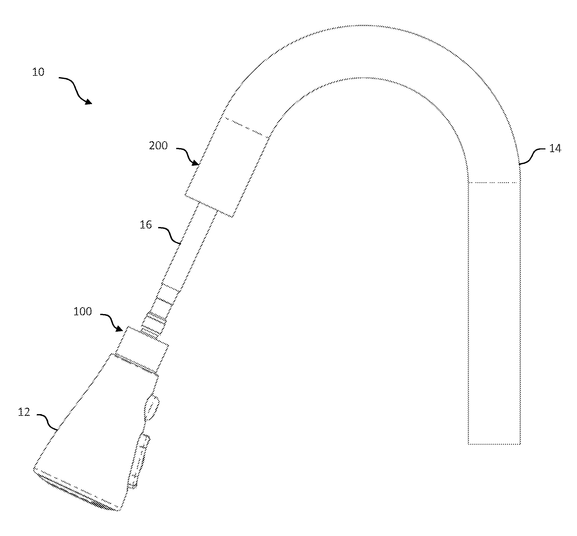
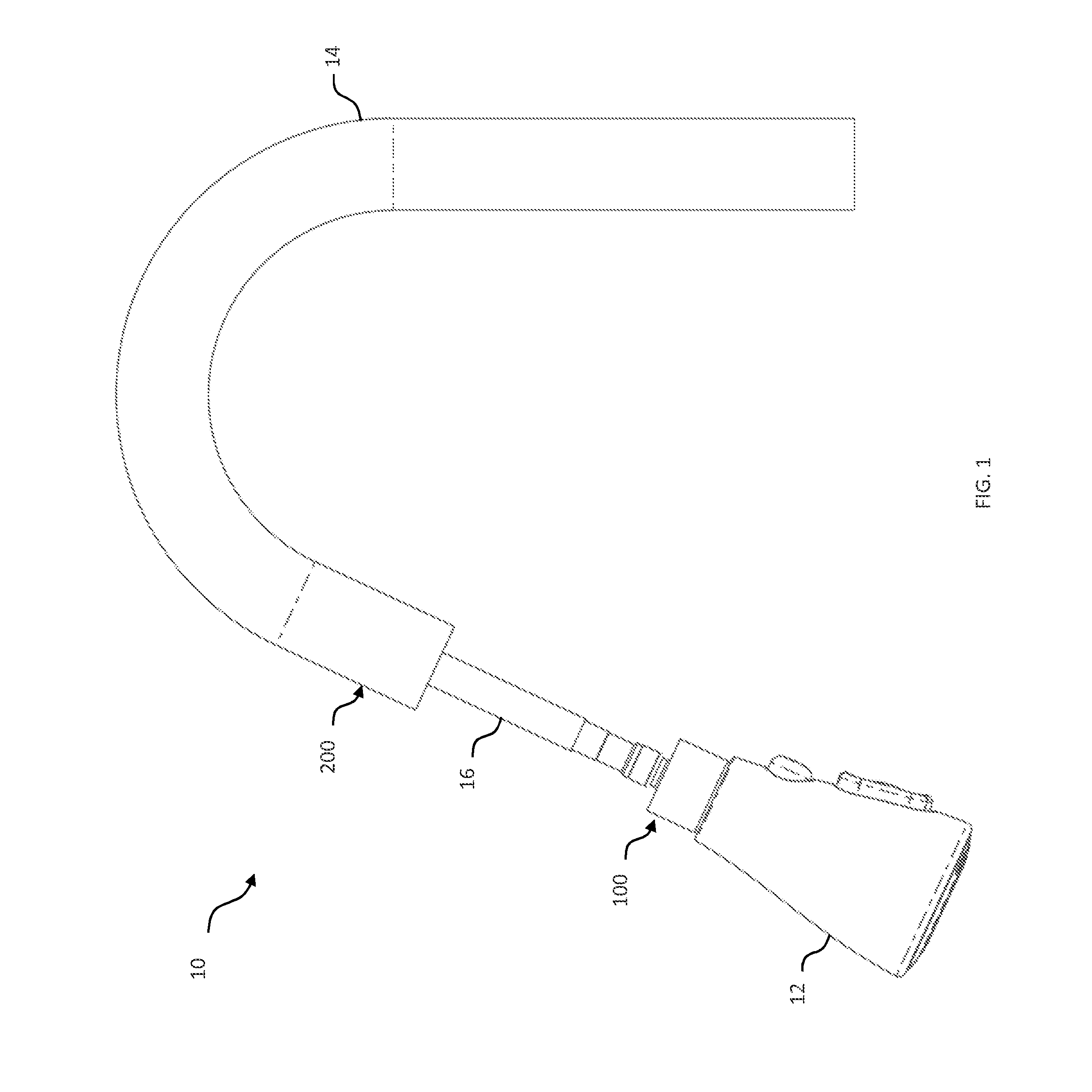
[0025]Referring now to the drawings, FIG. 1 shows a side view of faucet 10 having a faucet body 14, a hose 16, and an auto-retracting spray head 12 with an adapter 100, and docking assembly 200, in accordance with some embodiments of the present invention. Auto-retracting spray head 12, shown in an extended position, may be detachably coupled to faucet body 14 with docking assembly 200, which can assist in automatically docking adapter 100 (and thereby spray head 12) to faucet body 14 as described in detail hereinafter. During operation, water can flow through hose 16, an internal conduit of adapter 100, and out a tap of auto-retracting spray head 12 regardless of whether the spray head is in an extended position or a docked position relative to faucet body 14.

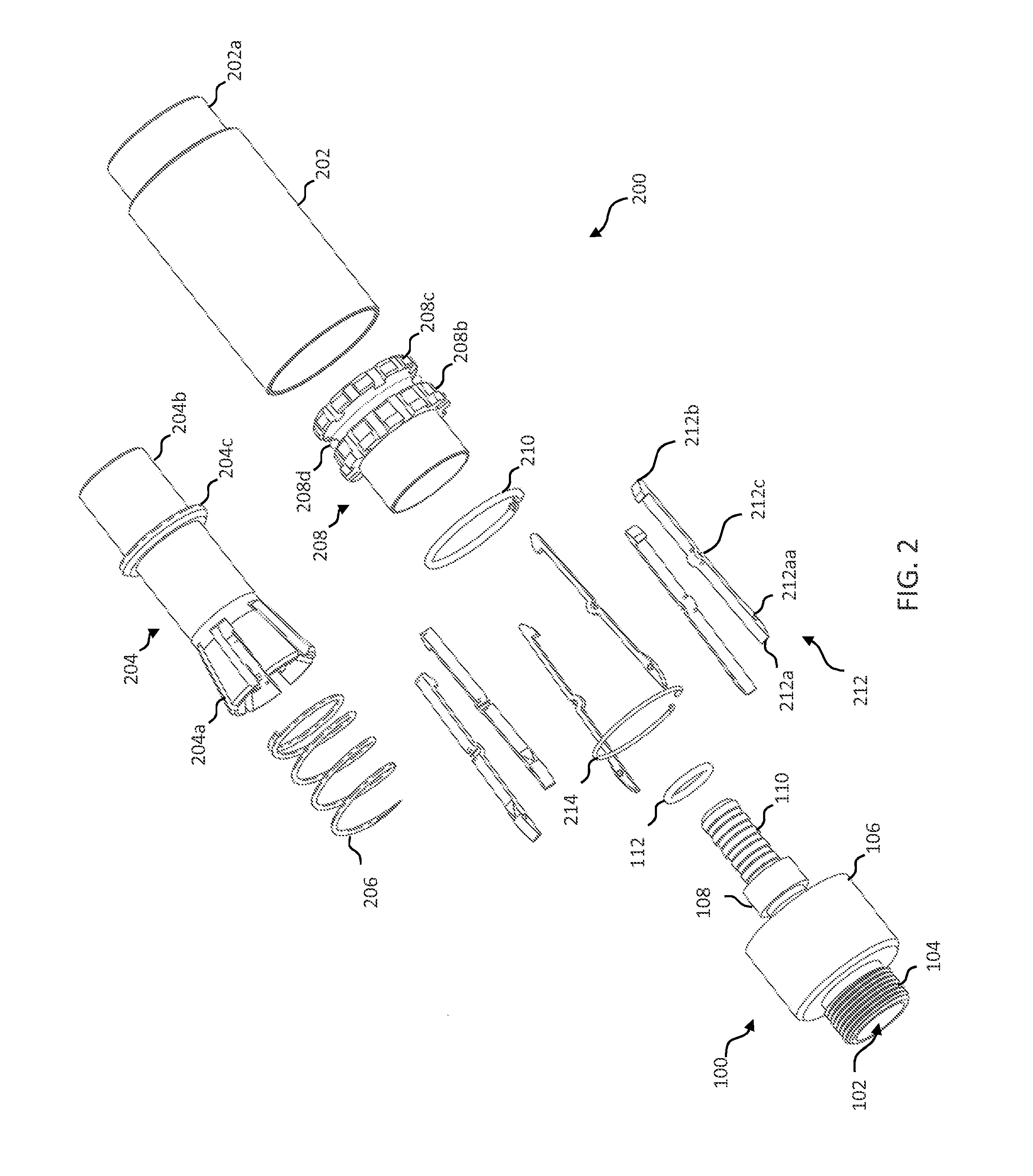
[0026]FIG. 2 shows an exploded view and FIG. 3 shows a cross-sectional view of adapter 100 and docking assembly 200, in accordance with some embodiments of the present invention. Adapter 100 may include internal conduit 102 fo...


PUM


Abstract

An auto-retracting faucet spray head has an auto-retract mechanism, which includes a docking assembly provided at the end of the faucet body to facilitate automatic retraction and docking of the spray head. The docking assembly includes a spring-loaded mechanism that automatically docks the spray head to the faucet body when an adapter coupled to the spray head engages the docking assembly.

Description

CROSS-REFERENCE TO RELATED APPLICATIONS[0001]This application claims the benefit of U.S. Provisional Patent Application 62 / 054,141, entitled “AUTO-RETRACTING MECHANISM FOR FAUCET SPRAY HEAD,” filed Sep. 23, 2014, the disclosure of which is incorporated by reference herein in its entirety.FIELD OF THE INVENTION[0002]The present invention generally relates to auto-retracting spray heads for faucets.BACKGROUND OF THE INVENTION[0003]Many commercially available faucets come equipped with pull-out spray heads that can help to ease the process of cleaning items placed under the tap. Typical faucets with pull-out spray heads use counterweights to assist in hose retraction. With such constructions, the spray heads may not fully retract to their docking positions due to hose friction and / or alignment issues between the spray heads and the spout tubes. Detents or magnets can be employed to assist in docking the spray heads to the faucet bodies; however, such mechanisms may not be optimal.SUMMA...

Claims


Application Information

Patent Timeline
Patent Type & Authority Applications(United States)
IPC IPC(8): E03C1/04B65H75/34
CPCE03C1/0404E03C2001/0417B65H75/34E03C2001/0415E03C1/04
Inventor LI, HSIAO, CHANG
Owner AS AMERICA
Why Eureka
Try Eureka