
Method for controlling a hydrodynamic retarder that can be mechanically disengaged by a disconnect clutch

a technology of disengagement clutch and hydrodynamic retarder, which is applied in the direction of hydrodynamic brakes, coupling-brake combination, liquid resistance brakes, etc., can solve the problems of undesirable wear and tear characteristics of the disengagement clutch, the need to bridge the great speed difference with the disengagement clutch,

Active Publication Date: 2016-03-24
VOITH PATENT GMBH
View PDF0 Cites 3 Cited by
  • Summary
  • Abstract
  • Description
  • Claims
  • Application Information

AI Technical Summary

Benefits of technology

The present invention provides a method for preventing heavy load on the disconnect clutch during synchronization efforts, which can occur when the retarder is fully engaged and the working chambers are filling with working medium. The method ensures that the working chamber is always filled to a predetermined level, which prevents wear and tear on the disconnect clutch during low-speed driving. The method also includes engaging the disconnect clutch to avoid high wear and tear during start-up of the vehicle. The invention monitors the rotational speed of the rotor or counter-rotating rotor and engages the disconnect clutch when a predetermined speed is reached. This ensures that the disconnect clutch is always engaged for efficient synchronization and reduces wear and tear on the clutch.

Problems solved by technology

Such an extensive synchronization effort occurs when during synchronization—that is during engaging of the disconnect clutch—on the one hand the working chamber of the retarder fills with working medium, in particular fills completely and on the other hand a great speed difference has to be bridged with the disconnect clutch.
If the disconnect clutch engages only when exceeding a predefined rotational speed of the rotor of the hydrodynamic retarder or a predefined vehicle speed, then the undesirable wear and tear characteristics occur in the disconnect clutch.

Method used


Image

  • Method for controlling a hydrodynamic retarder that can be mechanically disengaged by a disconnect clutch
  • Method for controlling a hydrodynamic retarder that can be mechanically disengaged by a disconnect clutch

Examples


Embodiment Construction

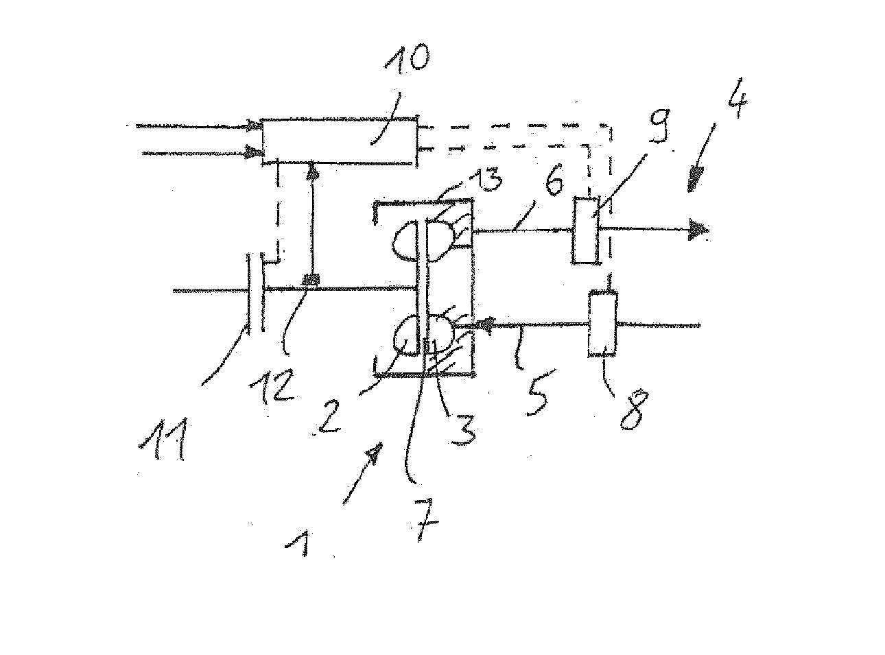
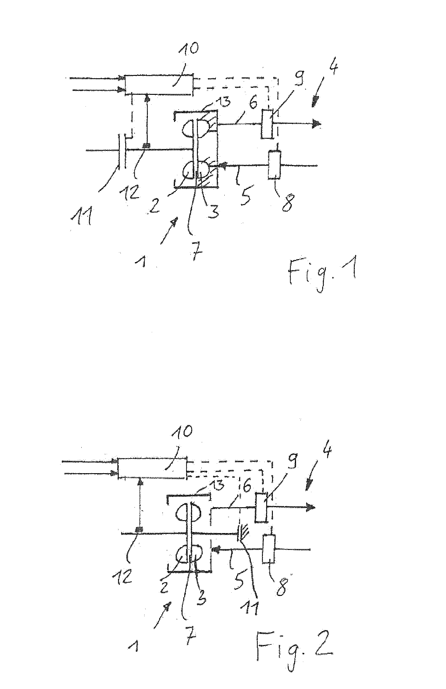
[0036]FIG. 1 illustrates a hydrodynamic retarder 1 with a rotor 2 and a stator 3. The working medium is fed via a working medium feed line 5 from an external working medium circuit 4 into working chamber 7; and for cooling of the working medium that was heated in working chamber 7 is removed from retarder 1 via a working medium outlet 6. An inlet valve 8 is arranged in working medium feed line 5 and a retarder outlet valve 9 is provided in working medium outlet line 6. Retarder controller 10 accesses retarder inlet valve 8 as well as also retarder outlet valve 9, at least indirectly. Retarder inlet valve 8 is disengaged for the transition from the non-braking mode to the braking mode. Retarder outlet valve 9 is activated by a signal pressure in such a way that it causes the desired accumulation of working medium and thus the desired fill level in working chamber 7. Alternatively, a filling level control by means of a pressure application that displaces a working medium supply could ...


PUM


Abstract

A method for controlling a hydrodynamic retarder in a motor vehicle that can be mechanically disengaged via a disconnect clutch, whereby at least one of the rotational speed of a revolving bladed rotor and the speed of a motor vehicle is monitored and a disconnect clutch is engaged below at least one of a pre-specified rotational speed of the revolving bladed rotor and a pre-specified speed of the motor vehicle, regardless of a request made by a driver assist system or by operation of an input device by the operator of the motor vehicle to turn on the hydrodynamic retarder.

Description

CROSS REFERENCE TO RELATED APPLICATIONS[0001]This is a continuation of PCT application No. PCT / EP2014 / 057579, entitled “METHOD FOR CONTROLLING A HYDRODYNAMIC RETARDER THAT CAN BE MECHANICALLY DISENGAGED BY A DISCONNECT CLUTCH”, filed Apr. 15, 2014, which is incorporated herein by reference.BACKGROUND OF THE INVENTION[0002]1. Field of the Invention[0003]The invention relates to a method for controlling a hydrodynamic retarder in a motor vehicle that can be mechanically disengaged via a disconnect clutch.[0004]2. Description of the Related Art[0005]In order to reduce the no-load losses of a hydrodynamic retarder to zero, it has already been suggested to disengage the hydrodynamic retarder during a non-braking mode by means of a disconnect clutch from the drive train which it is intended to brake in the braking-mode. During the transition from braking mode to non-braking mode, the working chamber is at the same time drained of working medium which, in the braking mode transfers a hydro...

Claims


Application Information

Patent Timeline
Patent Type & Authority Applications(United States)
IPC IPC(8): F16D67/02F16D57/00F16D57/02
CPCF16D67/02F16D57/005F16D57/02B60T10/02F16D57/04
Inventor ADAMS, WERNERLAUKEMANN, DIETERMENNE, ACHIMSCHADE, RAVI
Owner VOITH PATENT GMBH
Learn More