Optical sensor and optical sensor system

a technology of optical sensors and optical sensors, applied in the field of optical sensors, can solve the problems of ineffective reduction of the method is expensive and the system size is larger, and the size and cost of the gesture recognition module are large, etc., and achieve the effect of small size and low cos

Active Publication Date: 2016-03-24
PIXART IMAGING INC
View PDF5 Cites 15 Cited by
  • Summary
  • Abstract
  • Description
  • Claims
  • Application Information

AI Technical Summary

Benefits of technology

[0008]Accordingly, the present disclosure provides an optical sensor and an optical sensor system having the advantages of low cost and small size.

Problems solved by technology

However, these methods have a higher cost and a larger system size.
In this technique, two image sensors are used such that the size and cost of a gesture recognition module can not be effectively reduced.

Method used


Image

  • Optical sensor and optical sensor system
  • Optical sensor and optical sensor system
  • Optical sensor and optical sensor system

Examples


Embodiment Construction

[0020]It should be noted that, wherever possible, the same reference numbers will be used throughout the drawings to refer to the same or like parts.

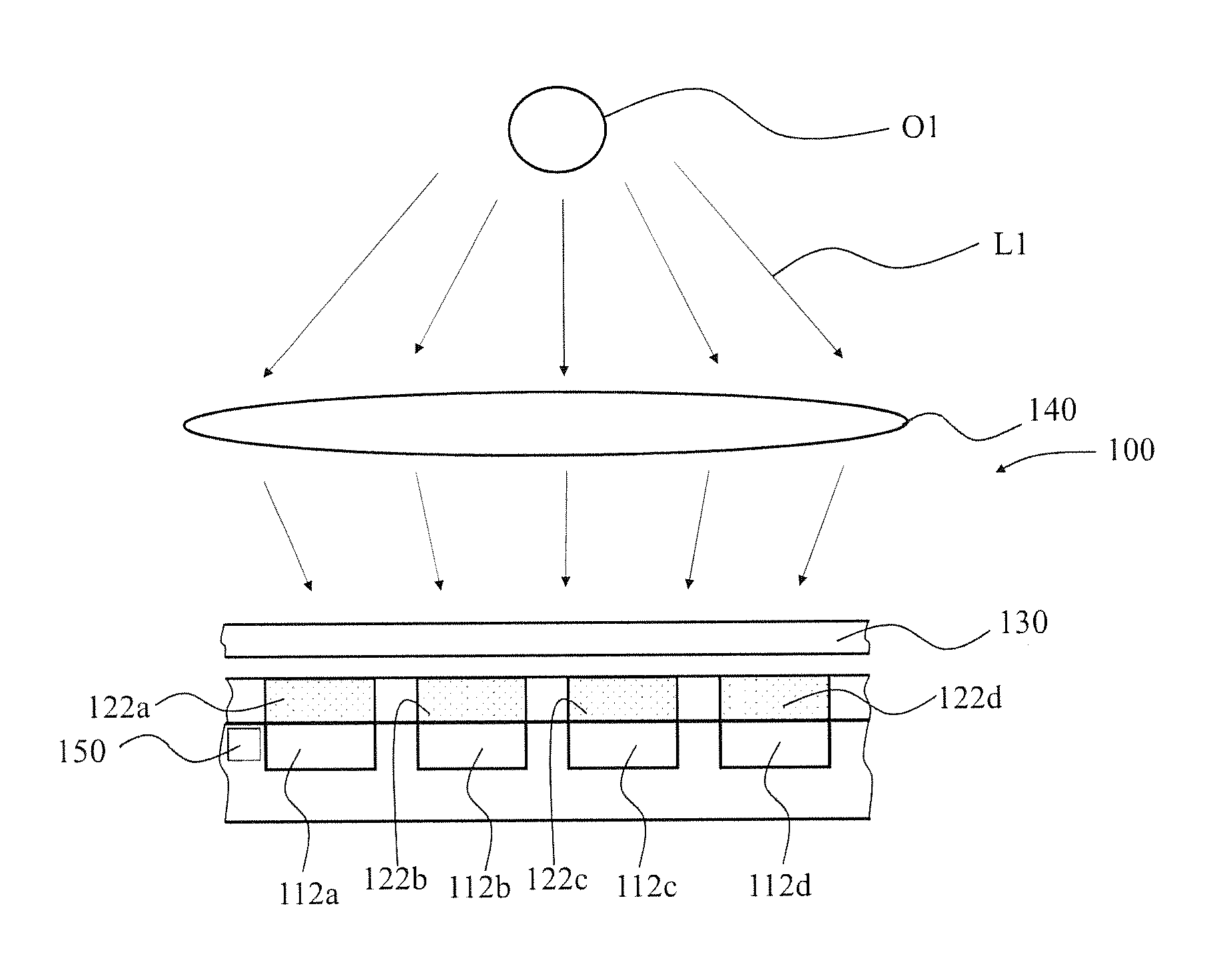
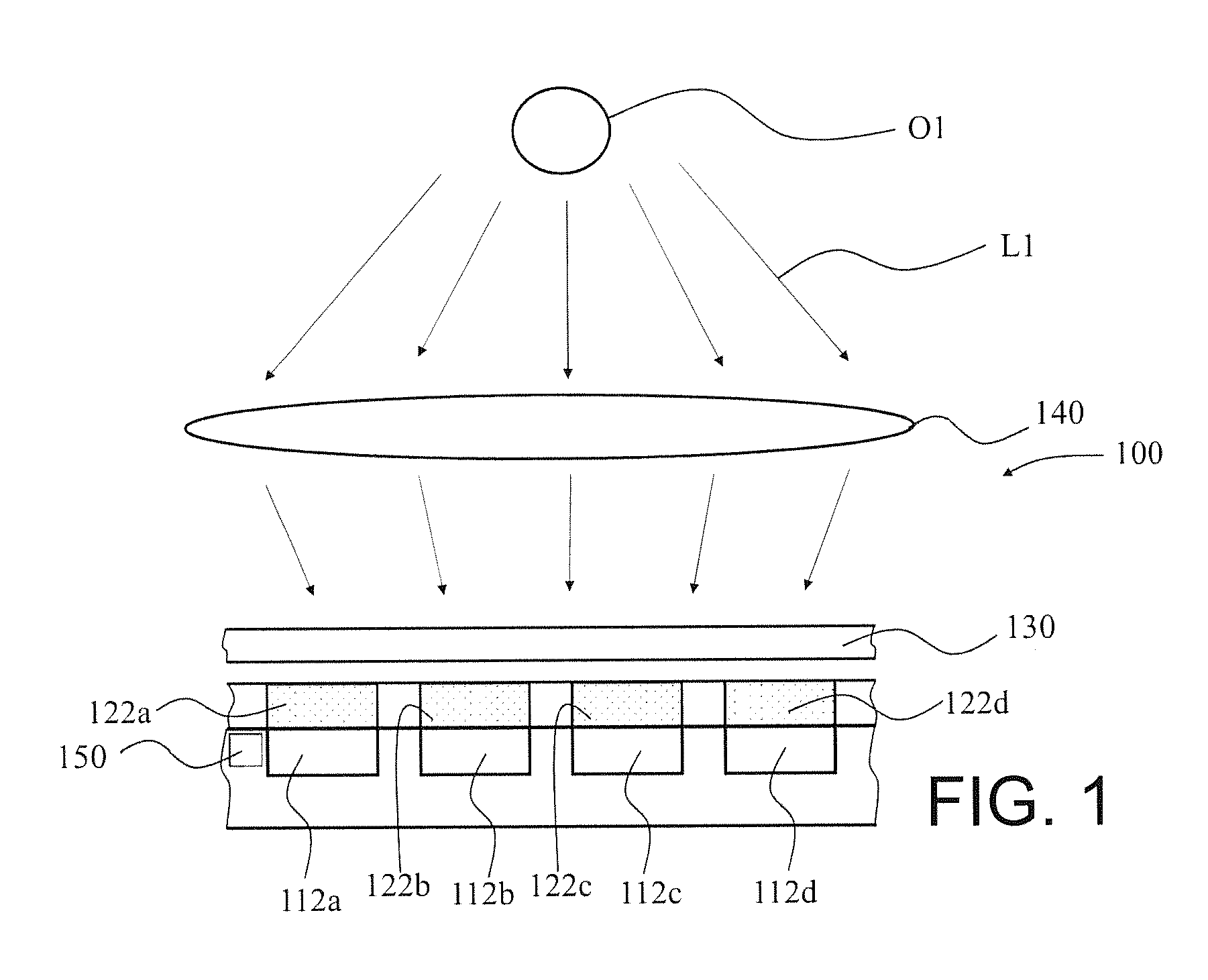
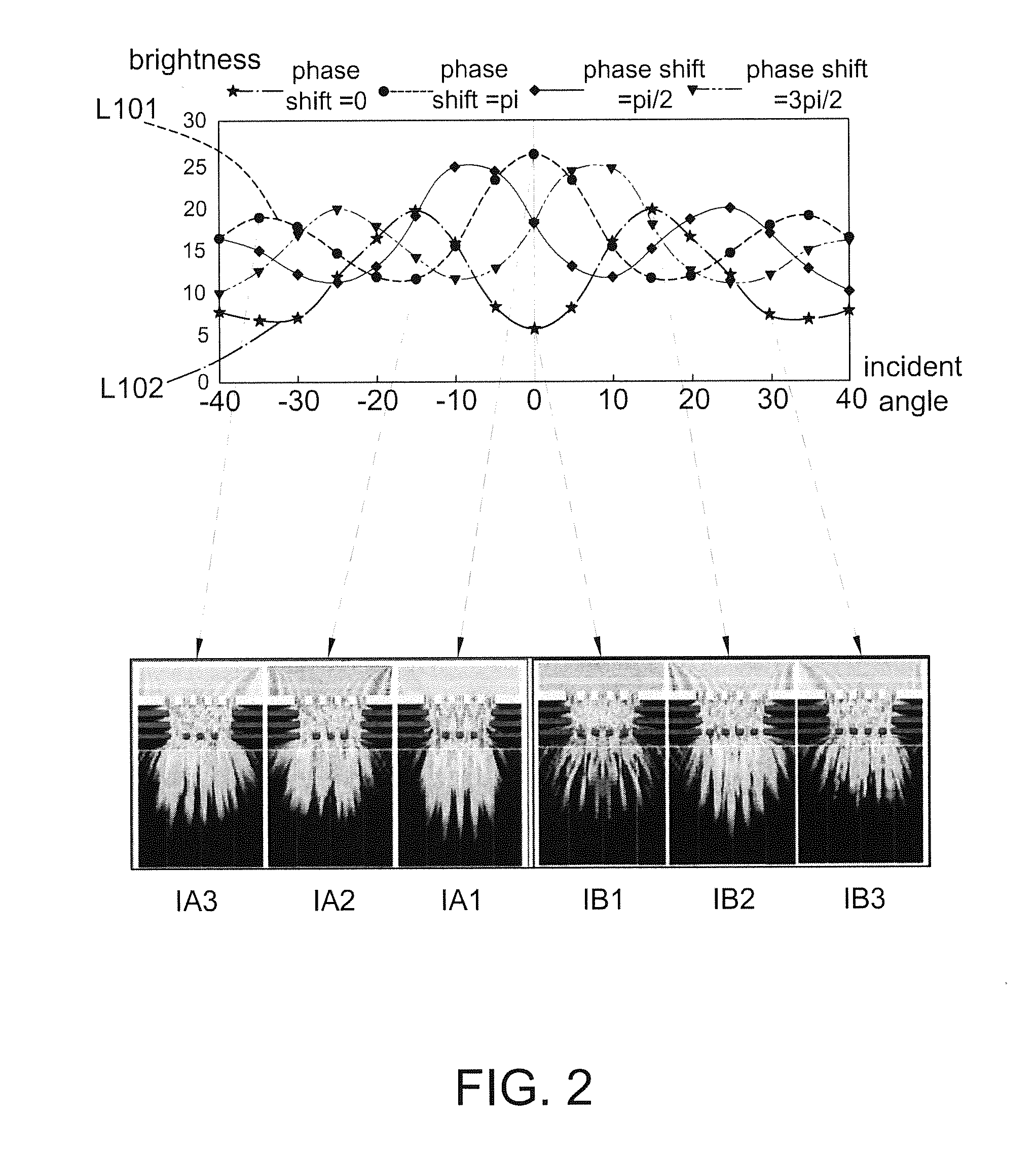
[0021]FIG. 1 is a schematic diagram of an optical sensor according to one embodiment of the present disclosure, and FIG. 2 is a schematic diagram of the intensity variation of light beams in different angles passing through grating elements of different phase shifts, wherein said grating elements of different phase shifts are, for example, shown in FIG. 3A to FIG. 3D.

[0022]Referring to FIG. 1, the optical sensor 100 of this embodiment includes at least two optical sensing pixels (e.g. four optical sensing pixels 112a, 112b, 112c and 112d shown herein, but not limited thereto), wherein each of the optical sensing pixels 112a, 112b, 112c and 112d respectively corresponds to a grating element 122a, 122b, 122c and 122d thereupon. A phase shift between these grating elements 122a, 122b, 122c and 122d is, for example, 0 degree, 90 degrees, 18...


PUM


Abstract

An optical sensor includes at least two optical sensing pixels and at least two different grating elements. These grating elements are disposed above these optical sensing pixels correspondingly.

Description

RELATED APPLICATIONS[0001]The present application is based on and claims priority to Taiwanese Application Number 103133154, filed Sep. 24, 2014 and Taiwanese Application Number 104102611, filed Jan. 26, 2015, the disclosures of which are hereby incorporated by reference herein in their entirety.BACKGROUND[0002]1. Field of the Disclosure[0003]This disclosure generally relates to an optical sensor and, more particularly, to an optical sensor and an optical sensor system adaptable to a distance measurement or a gesture recognition.[0004]2. Description of the Related Art[0005]In general, a distance measurement system employs a light source and calculates an object distance according to energy of the light beam of the light source reflected back by the object. Traditionally, it is able to use the triangulation method or time-of-flight (TOF) technique to calculate the distance. However, these methods have a higher cost and a larger system size.[0006]In addition, the development of gestur...

Claims


Application Information

Patent Timeline
Patent Type & Authority Applications(United States)
IPC IPC(8): G01C3/08G01J1/44
CPCG01J1/44G01C3/08G01S3/7803G01S3/783
Inventor HSU, EN-FENGLIU, CHIA-YU
Owner PIXART IMAGING INC
Why Eureka
Try Eureka