Liquid ejection head driving system

a driving system and liquid ejection technology, applied in printing, inking apparatus, other printing apparatus, etc., can solve the problems of inability to provide shield wire, increase in cost of flexible cables, and inability to implement shield wires to wire substrates, etc., to achieve the effect of convenient attachmen

Inactive Publication Date: 2016-03-31
FUJIFILM CORP
View PDF2 Cites 21 Cited by
  • Summary
  • Abstract
  • Description
  • Claims
  • Application Information

AI Technical Summary

Benefits of technology

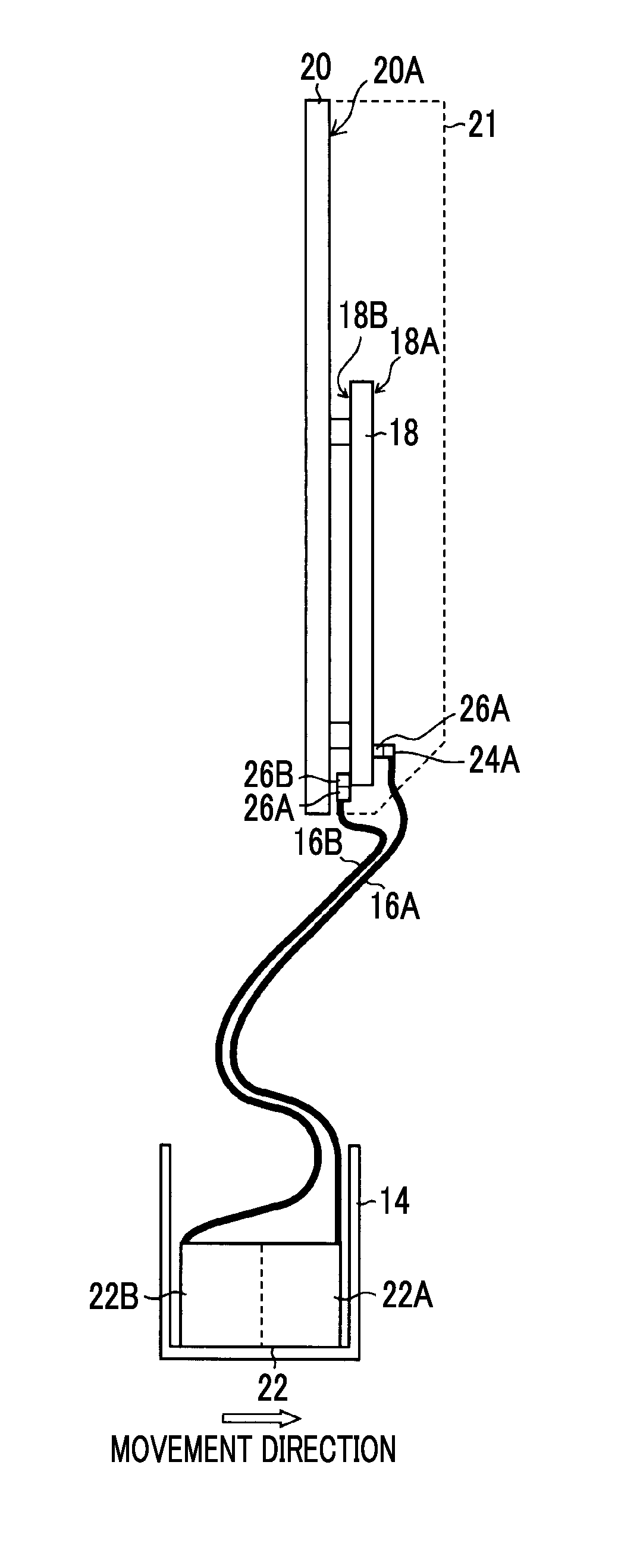
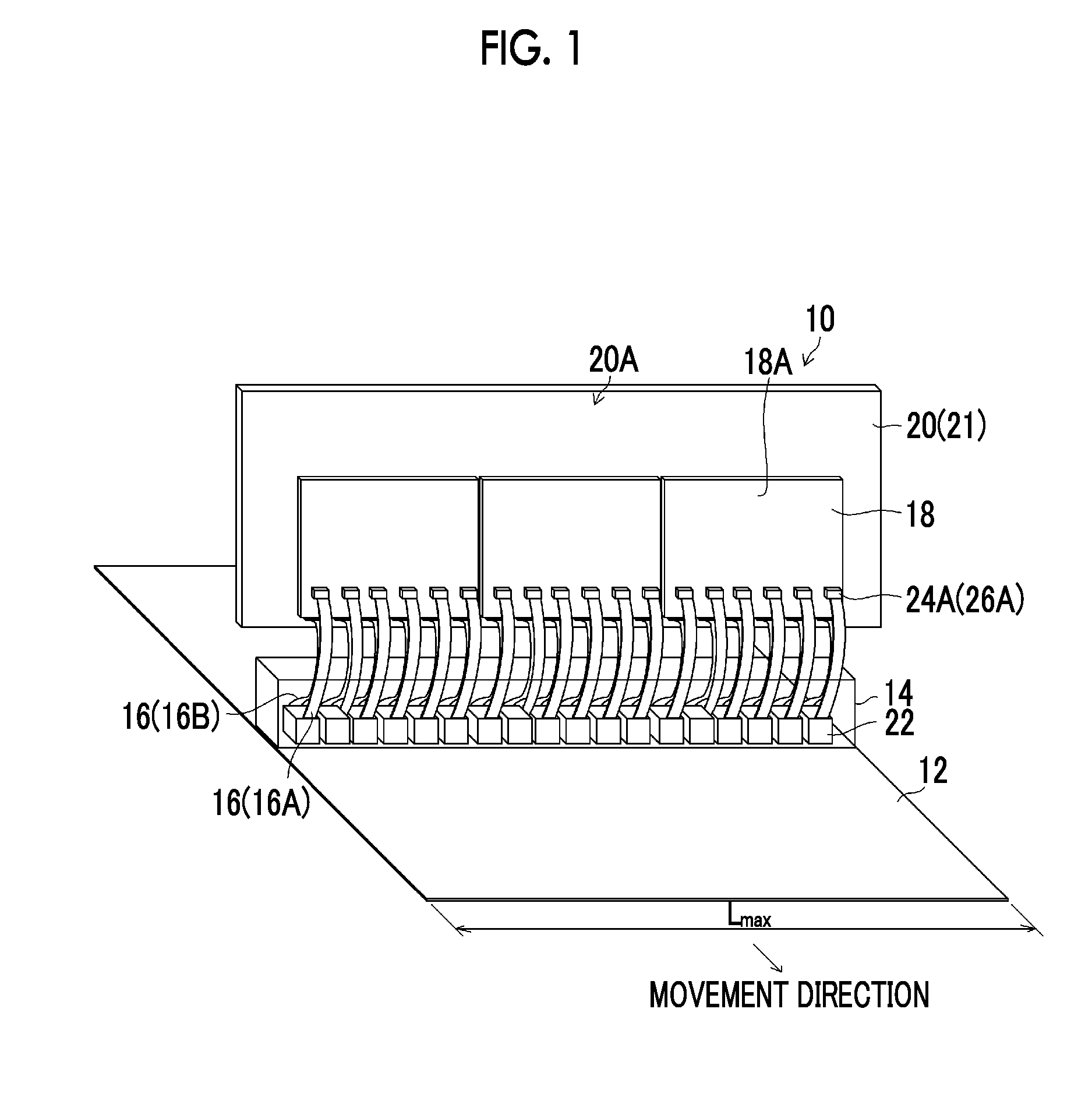
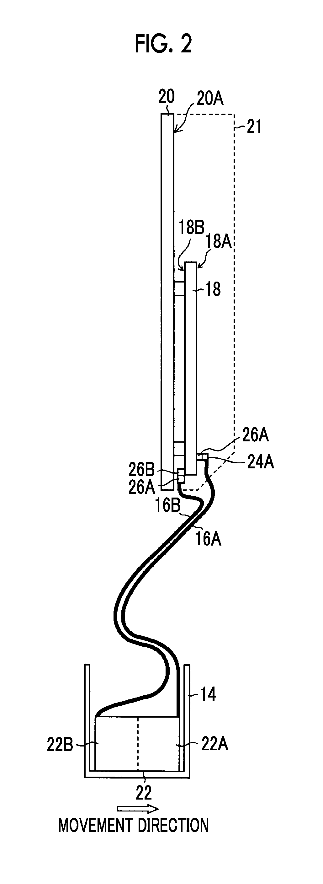
[0022]In addition, since the driving circuit substrate has the circuit-side connector mounted at a position where the direction of insertion and extraction of the wiring-side connector provided in the wiring substrate is released, it is possible to easily perform the attachment and detachment of the wiring substrate to and from the driving circuit substrate during maintenance, without any interference when the wiring-side connector is inserted and extracted.

Problems solved by technology

Generally, when the wiring substrate is disposed with the same width as that of the ink jet head, a space in which the wiring substrate is disposed is limited, and thus the addition of a shield wire (shield electrode) to the wiring substrate may not be able to implemented by restrictions on the space in which the wiring substrate is disposed.
In addition, the flexible cable becomes thicker by providing the shield wire, and the shield wire is not able to be provided by restrictions on the arrangement space of the flexible cable.
Further, the flexible cable is provided with the shield wire, and thus the flexible cable increases in cost.

Method used


Image

  • Liquid ejection head driving system
  • Liquid ejection head driving system
  • Liquid ejection head driving system

Examples


thirteenth aspect

[0258](Thirteenth Aspect) In the liquid ejection head driving system according to any one of the first aspect to the twelfth aspect, the plurality of wiring substrates are configured such that the driving signal patterns thereof are equal to each other, and that lengths of the reference potential patterns thereof are equal to each other.

[0259]According to the thirteenth aspect, a wiring length for each system within the driving circuit substrate, a wiring length for each system in the wiring substrate, and a wiring length for each system within the liquid ejection head are made to be equal to each other, and thus the generation of electromagnetic waves (electromagnetic noise) generated in each unit is suppressed.


PUM


Abstract

A liquid ejection head driving system includes an ink jet head, a driving circuit substrate provided with a driving circuit in which a driving signal is generated, a driving signal wiring that branches an output of the driving circuit into two or more systems, and a plurality of connectors that extract the driving signal wiring for each system, and a flexible flat substrate (FFC) in which a connector connected to a connector of the driving circuit substrate is installed, a driving signal pattern for transmitting the driving signal for each system is formed on a first layer, and a reference potential pattern is formed on a second layer. The driving circuit substrate is configured such that the same number of connectors as the number of wiring substrates are mounted at a position where a direction of insertion and extraction of the connector of the FFC is released.

Description

CROSS-REFERENCE TO RELATED APPLICATIONS[0001]The present application is a Continuation of PCT International Application No. PCT / JP2014 / 058442 filed on Mar. 26, 2014 claiming priority under 35 U.S.C §119(a) to Japanese Patent Application No. 2013-077084 filed on Apr. 2, 2013. Each of the above applications is hereby expressly incorporated by reference, in their entirety, into the present application.BACKGROUND OF THE INVENTION[0002]1. Field of the Invention[0003]The present invention relates to a liquid ejection head driving system, and particularly relates to a driving circuit substrate that supplies a driving signal (drive voltage) to a liquid ejection head and a wiring substrate that connects the liquid ejection head and the driving circuit substrate.[0004]2. Description of the Related Art[0005]As one of image forming methods in an ink jet recording apparatus, a method is known of using a (full) line-type ink jet head having a structure in which a plurality of nozzles that eject d...

Claims


Application Information

Patent Timeline
Patent Type & Authority Applications(United States)
IPC IPC(8): B41J2/045
CPCB41J2/04586B41J2/04541B41J2/14233B41J2/155B41J2002/14241B41J2002/14266B41J2002/14459B41J2002/14491B41J2/18B41J2/04581B41J2202/12B41J2202/20
Inventor TANAKA, HISAYUKI
Owner FUJIFILM CORP
Why Eureka
Try Eureka