Fiber optic and slip ring rotary joint for suspension arm

a technology of slip ring and suspension arm, which is applied in the field of infinite rotation of fiber optic and slip ring joints, can solve the problems of not allowing for a large data transfer rate of transmitted through the supports to the devices

Active Publication Date: 2016-03-31
STRYKER CORP
View PDF12 Cites 30 Cited by
  • Summary
  • Abstract
  • Description
  • Claims
  • Application Information

AI Technical Summary

Problems solved by technology

Alternatively, if the rotation of the joints allowed for a larger range of rotation, such arrang...

Method used


Image

  • Fiber optic and slip ring rotary joint for suspension arm
  • Fiber optic and slip ring rotary joint for suspension arm
  • Fiber optic and slip ring rotary joint for suspension arm

Examples


Embodiment Construction

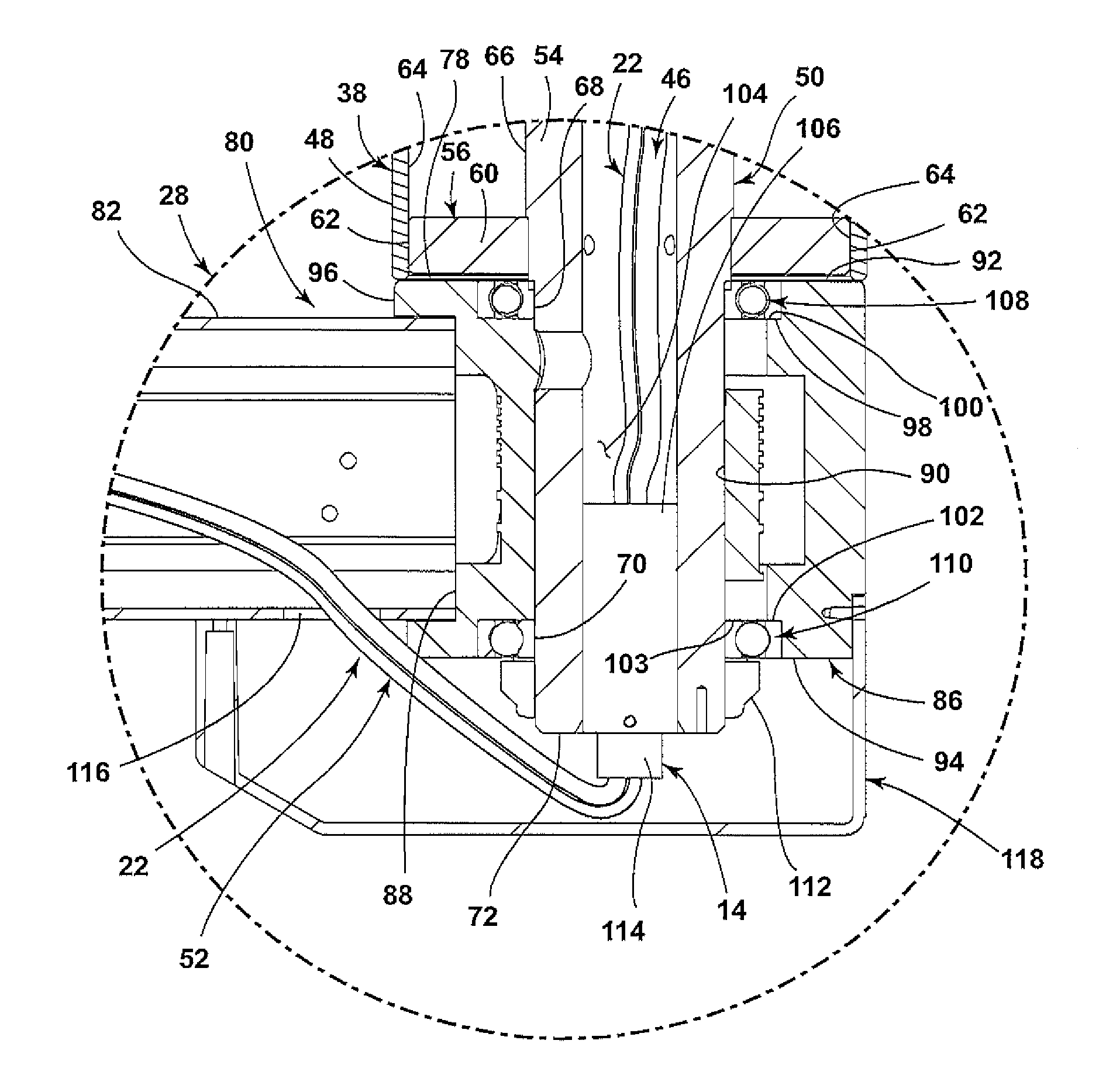
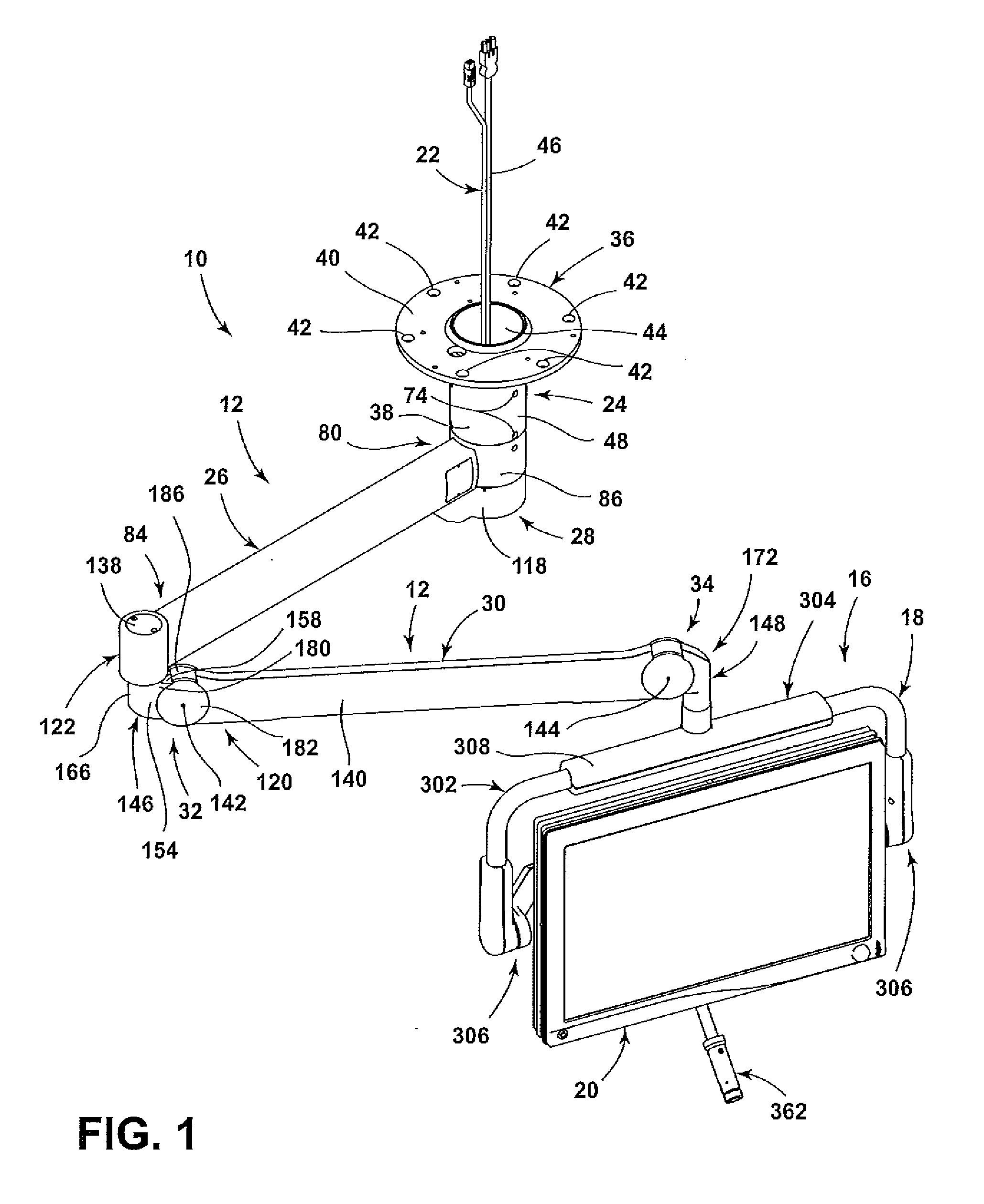
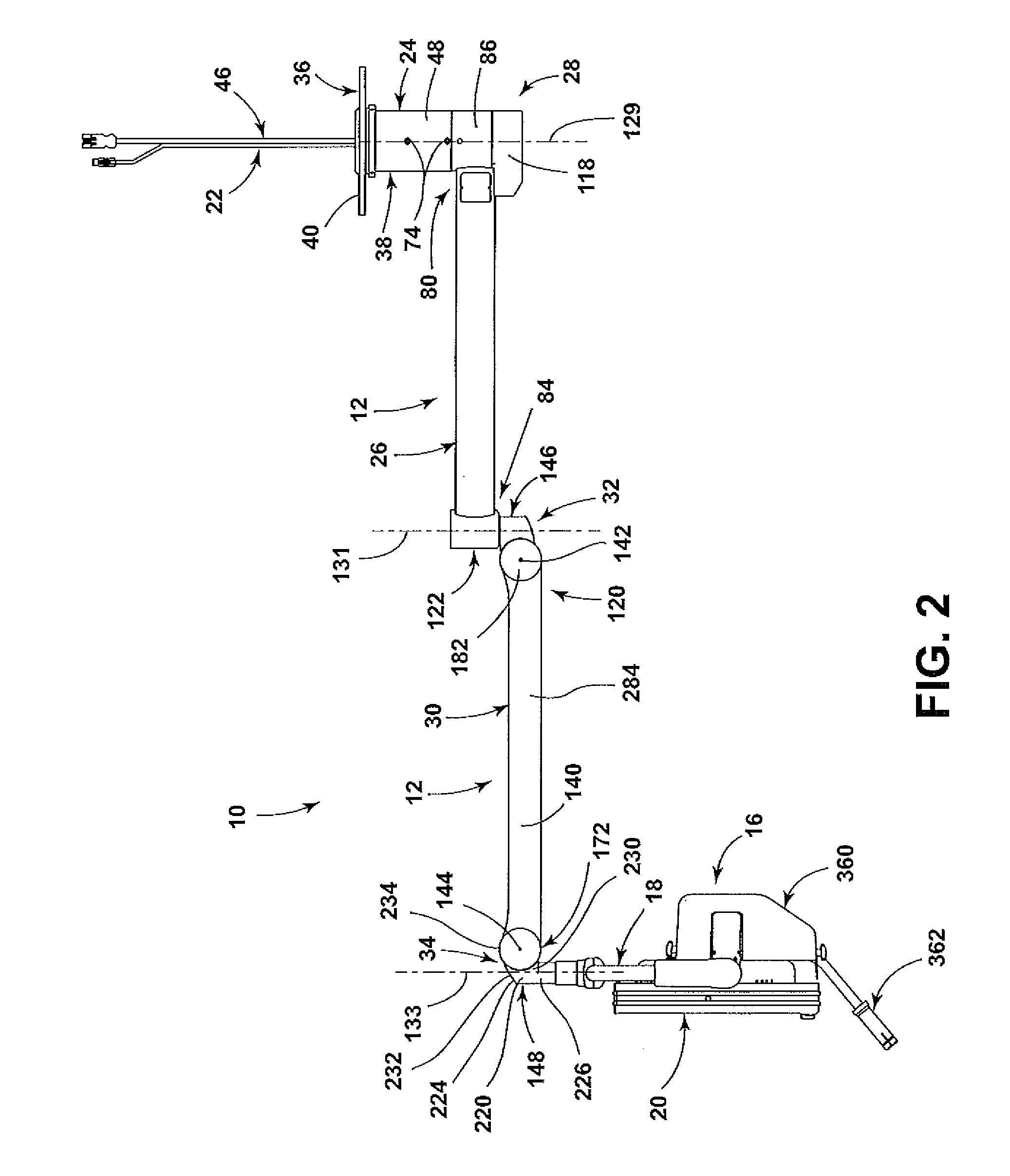
[0021]The reference number 10 (FIGS. 1-4) generally designates a suspension arm assembly of the present invention. The suspension arm assembly 10 includes a ceiling attachment member 24, a wired medical unit 16 and a plurality of arms 12 between the ceiling attachment member 24 and the wired medical unit 16. The intersections between one of the arms 12 and the ceiling attachment member 24, each of the arms 12, and one of the arms 12 and the wired medical unit 16 allow for infinite rotation. Each intersection also includes an infinite rotation fiber optic and slip ring joint 14 (see FIGS. 3 and 4) therein. A cabling system 22 transmits data and power through the suspension arm assembly 10 to the wired medical unit 16 and the infinite rotation fiber optic and slip ring joints 14 allow for unlimited rotation of the arms 12 and the wired medical unit 16.

[0022]The illustrated suspension arm assembly 10 is configured to be positioned within a room (e.g., an operating room) and, in the ill...


PUM


Abstract

A medical suspension arm assembly including a plurality of suspension arms, with each adjacent pair of the suspension arms being connected to each other by a joint and with at least one of the joints comprising an infinite rotation joint. The infinite rotation joint allows the suspension arms at the infinite rotation joint to have unlimited rotation relative to one another. Cabling including at least one fiber optic cable extends through each of the suspension arms and each joint. A wired medical unit is connected to an end of the plurality of suspension arms. High definition video, data and power can be transferred along each one of the suspension arms through the cabling and across each joint.

Description

CROSS REFERENCE TO RELATED APPLICATION[0001]This claims the benefit of U.S. Provisional Application Ser. No. 62 / 056,878, filed Sep. 29, 2014.FIELD OF THE INVENTION[0002]The present invention relates to a joint, and in particular to an infinite rotation fiber optic and slip ring joint that can be used in medical devices.BACKGROUND OF THE INVENTION[0003]Surgical monitors have been used in operating rooms to provide images to surgeons in the room. Likewise, other wired devices, such as surgical lights, speakers, joysticks, keyboards and cameras, have been used in operating rooms to provide surgical information to a surgeon or other person in the operating room (e.g., images from a camera or patient vital information). Such devices receive and / or provide signals and power to and / or from various supports mounted or provided in the operating room, thereby requiring wiring to extend through supports for such devices to the devices. Such wiring arrangements have necessitated that the rotati...

Claims


Application Information

Patent Timeline
IPC IPC(8): F16L3/015F16M13/02G02B6/36G02B6/44H04N7/015H04N7/10H04N7/22
CPCF16L3/015F16M13/027F16M13/02A61B19/26F16M2200/06G02B6/4461H04N7/22H04N7/10H04N7/015G02B6/3604F16M11/10F16M11/2014F16M11/2092F16M11/24F16M2200/044F16M2200/063F16M2200/065A61B90/50
Inventor BOCCOLERI, GIANNI, RONALDTIMOSZYK, WOJCIECH, K.CHASE, DAVID, P.
Owner STRYKER CORP
Why Eureka
Try Eureka