Optical system for a motor vehicle

Active Publication Date: 2016-03-31
VALEO VISION SA
View PDF7 Cites 3 Cited by
  • Summary
  • Abstract
  • Description
  • Claims
  • Application Information

AI Technical Summary

Benefits of technology

[0010]The invention therefore

Problems solved by technology

This type of configuration has a significant drawback: the light output obtained from this plurality of sources in turn presents a number of light shadows, each corresponding to a beam emit

Method used


Image

  • Optical system for a motor vehicle
  • Optical system for a motor vehicle
  • Optical system for a motor vehicle

Examples


Embodiment Construction

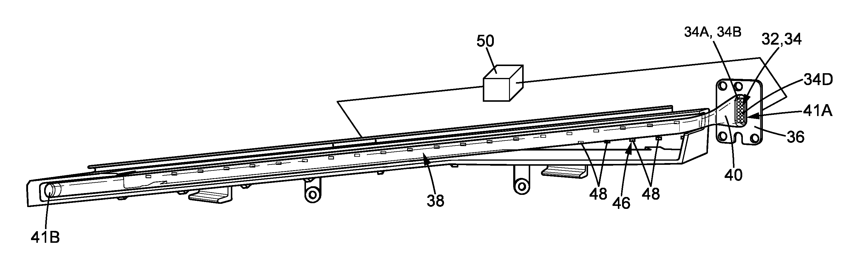
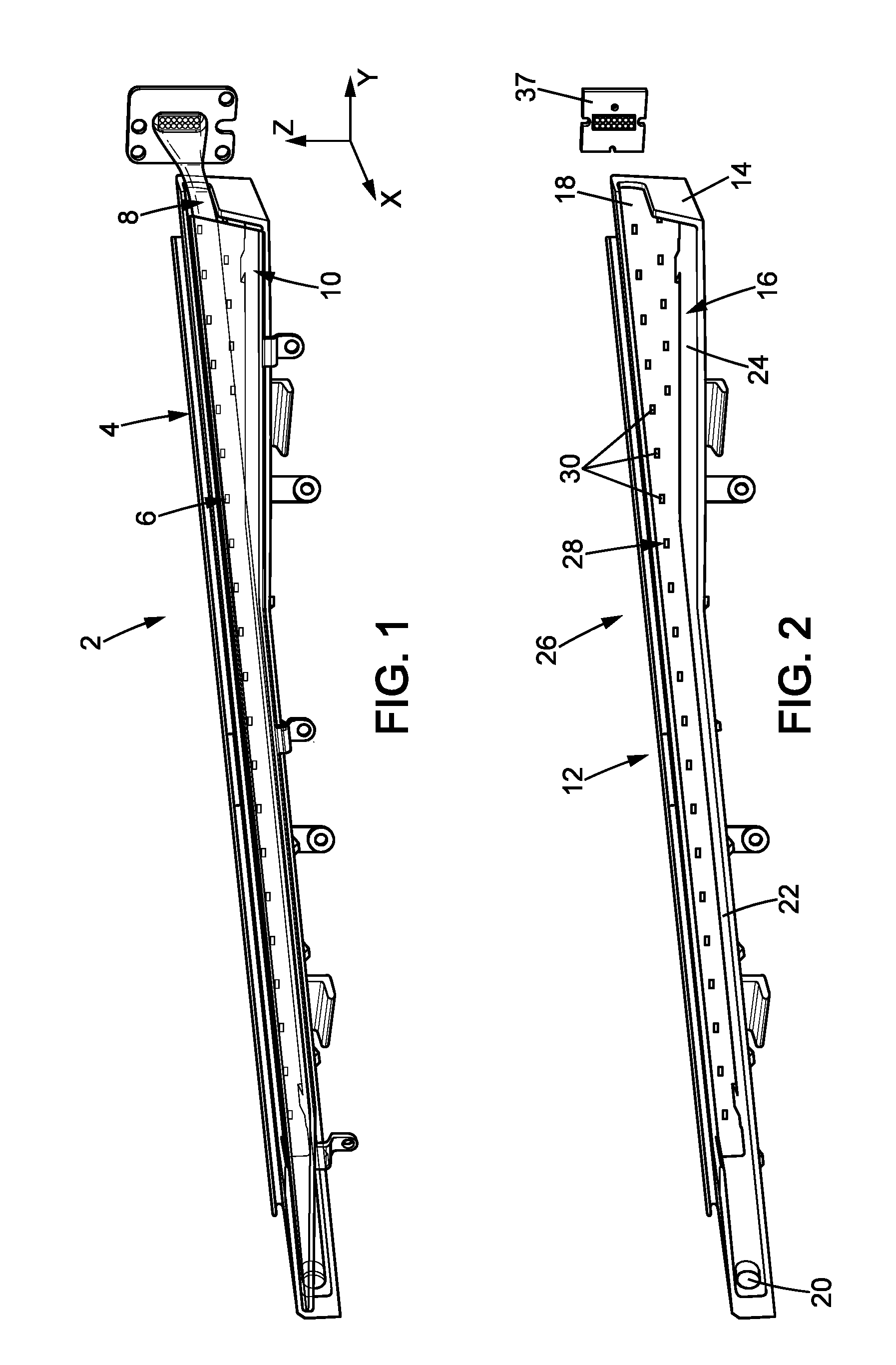
[0049]FIG. 1 illustrates an optical light emission system 2 according to the invention, referred to below as the system 2. FIG. 1 has a reference system of a trihedral XYZ.

[0050]The system 2 is intended to be fitted to a motor vehicle. The system 2 is configured to perform a function of external lighting of the vehicle. In particular, the system 2 has:[0051]a first operating mode of flashing lighting. This first operating mode is implemented for example to indicate a change of direction of the vehicle or to indicate a hazard situation;[0052]a second operating mode of daytime running lighting; and[0053]a third operating mode of position lighting.

[0054]These operating modes are explained below.

[0055]In practice, the system 2 is preferably a system commonly known as a “flasher” and which may serve to indicate that the vehicle is intending to change direction, to help indicate a hazard situation, to perform position lighting etc.

[0056]The system 2 is for example arranged at the front or...


PUM


Abstract

An optical light emission system for a motor vehicle, the optical system comprising:
    • a first light emission subsystem comprising a first set of light sources, and
    • a second light emission subsystem comprising a second set of light sources and a light guide able to diffuse the light from said light sources of the second set of light sources outside the optical system.
The light guide is arranged facing the first set of light sources such that the first set of light sources substantially radiates through the light guide outside the optical system.

Description

CROSS-REFERENCE TO RELATED APPLICATIONS[0001]This application claims priority to the French application 1459267 filed on Sep. 30, 2014, which application is incorporated herein by reference and made a part hereof.BACKGROUND OF THE INVENTION[0002]1. Field of the Invention[0003]The invention concerns an optical light emission system for a vehicle.[0004]2. Description of the Related Art[0005]Lighting systems fitted to vehicles are for example used to improve the visibility of the vehicle environment, to indicate the presence of the vehicle to other road users, to indicate that the vehicle is braking, or to indicate an intention to change the direction of movement of the vehicle.[0006]In modern systems used more particularly for the latter function, it is normal for the light source used to create the light beam, visible to people in the environment, to take the form of a plurality of light sources.[0007]This type of configuration has a significant drawback: the light output obtained fr...

Claims


Application Information

Patent Timeline
IPC IPC(8): F21S8/10F21V5/02F21V23/04
CPCF21S48/2281F21V5/02F21V23/0407F21Y2103/003F21S48/218F21W2101/12F21S48/215B60Q1/0058B60Q1/2607B60Q1/28B60Q2400/20B60Q2400/30F21Y2105/10F21Y2103/10F21Y2115/10F21Y2113/13G02B6/001F21S43/15F21S43/249F21S43/237F21S43/245F21W2103/20F21S43/14B60Q1/381G02B6/0005
Inventor DUBOSC, CHRISTOPHE
Owner VALEO VISION SA
Why Eureka
Try Eureka