

Serial bus electrical termination control
a technology of electrical termination control and serial bus, applied in the field of universal serial bus (usb) communication, can solve the problems of complicated circuit board layout, complicated control logic of usb controller of device or system,
- Summary
- Abstract
- Description
- Claims
- Application Information
AI Technical Summary
Benefits of technology
Problems solved by technology
Method used
Image

Examples
example 1
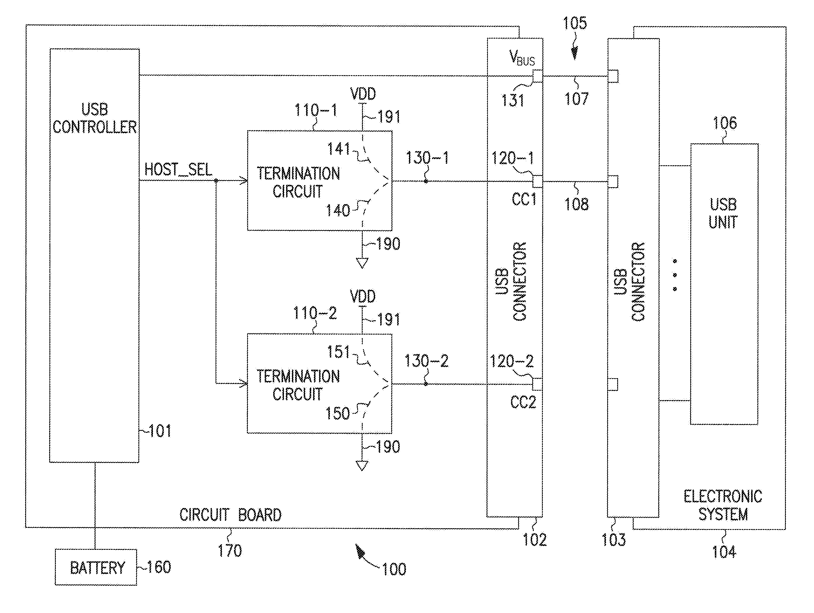
[0071 includes subject matter (such as a device, apparatus, or machine) comprising a node to couple to a serial bus, and a controller to provide a control signal to one of a first circuit path and a second circuit path in order to change electrical termination of a signal at the node between a first electrical termination through the first circuit path during a first mode of the controller and a second electrical termination through the second circuit path during a second mode of the controller without providing another control signal from the controller to the first and second circuit paths during the first and second modes.
[0072]In Example 2, the subject matter of Example 1 may optionally include, wherein the serial bus includes a Universal Serial Bus (USB).
[0073]In Example 3, the subject matter of Example 1 may optionally include, wherein.
[0074]In Example 4, the subject matter of any of Example 1 through Example 3 may optionally include, wherein.
example 5
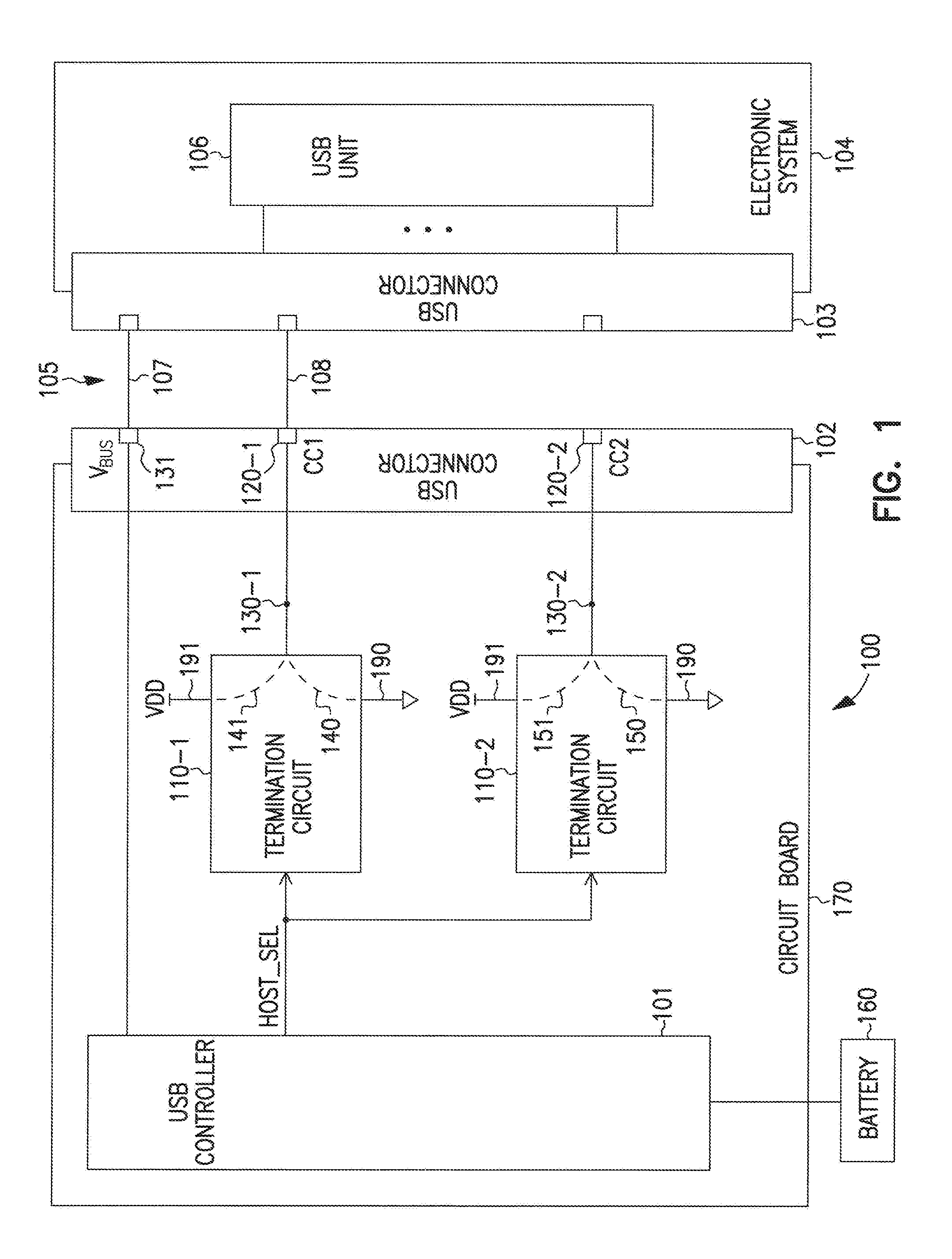
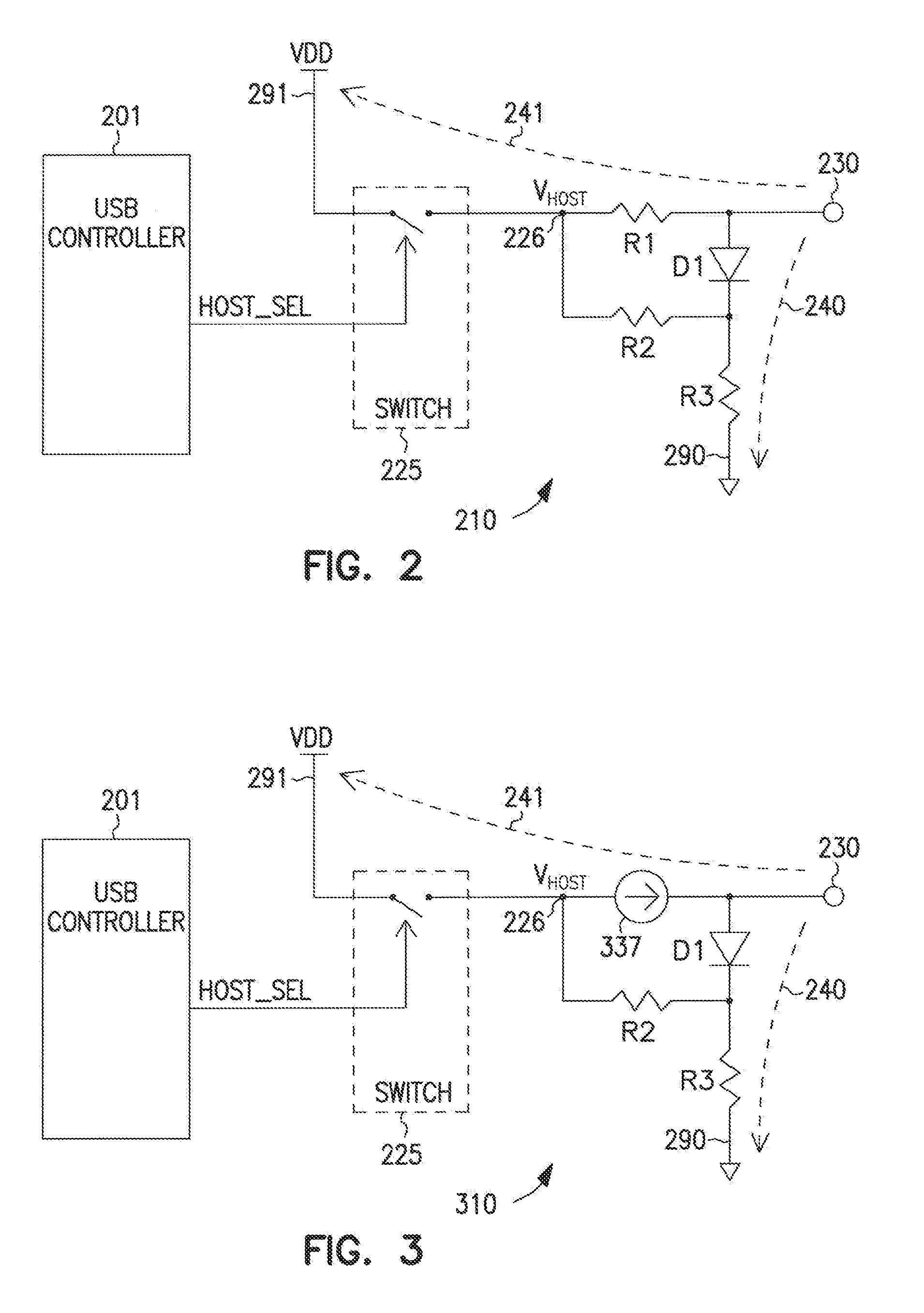
[0075 includes subject matter (such as a device, apparatus, or machine) comprising a node to couple to a Configuration Channel of a Universal Serial Bus (USB) connection, a first circuit path to terminate a signal at the node to a first supply node, and a second circuit path including a diode and a resistor to terminate the signal at the node to a second supply node.
[0076]In Example 6, the subject matter of Example 5 may optionally include, wherein the diode is arranged to be reversed biased when the signal at the node is terminated to the first supply node.
[0077]In Example 7, the subject matter of Example 5 or Example 6 may optionally include, wherein the diode is arranged to be forward biased when the signal at the node is terminated to the second supply node.
[0078]In Example 8, the subject matter of Example 5 may optionally include, wherein the first circuit path includes a current source coupled between the node and the first supply node.
[0079]In Example 9, the subject matter of...
example 12
[0082 includes subject matter (such as a device, apparatus, or machine) comprising a node to couple to a Configuration Channel of a Universal Serial Bus (USB) connection to receive a signal, a USB controller to provide a control signal to one of a first circuit path and a second circuit path in order to change electrical termination of a signal at the node between a first electrical termination through the first circuit path during USB host mode of the USB controller and a second electrical termination through the second circuit path during USB device mode of the USB controller, wherein the USB controller is arranged to provide the control signal to the first and second circuit paths during the USB host and device modes without providing another control signal from the USB controller to the first and second circuit paths during the USB host and device modes, a processor coupled to the USB controller, and an antenna coupled to the processor
[0083]In Example 13, the subject matter of E...
PUM
 Abstract
Description
Claims
Application Information