Auto-focus device and method for controlling operation of same

Active Publication Date: 2016-03-31
FUJIFILM CORP
View PDF3 Cites 9 Cited by
  • Summary
  • Abstract
  • Description
  • Claims
  • Application Information

AI Technical Summary

Benefits of technology

The invention aims to improve the experience of taking photos by preventing discomfort caused by switching between phase difference and contrast autofocus modes. The invention uses two different signals to estimate the focus position: one based on a phase difference imaging element, and another based on the optical path length difference. By calculating the difference between the estimated focus position and the position of the focus lens, the invention can smoothly bring the target subject into focus without causing rapid changes in the image area. This results in a higher quality photo.

Problems solved by technology

Therefore, an area to be brought into focus cannot be arbitrarily set.
Therefore, after focusing control is performed using the phase difference AF, when control is performed to bring an arbitrary area into focus through the contrast AF, an image area to be brought into focus at the time of the switching is also switched, and thus a target subject is not smoothly brought into focus.
As a result, this causes an uncomfortable feeling.

Method used


Image

  • Auto-focus device and method for controlling operation of same
  • Auto-focus device and method for controlling operation of same
  • Auto-focus device and method for controlling operation of same

Examples


Embodiment Construction

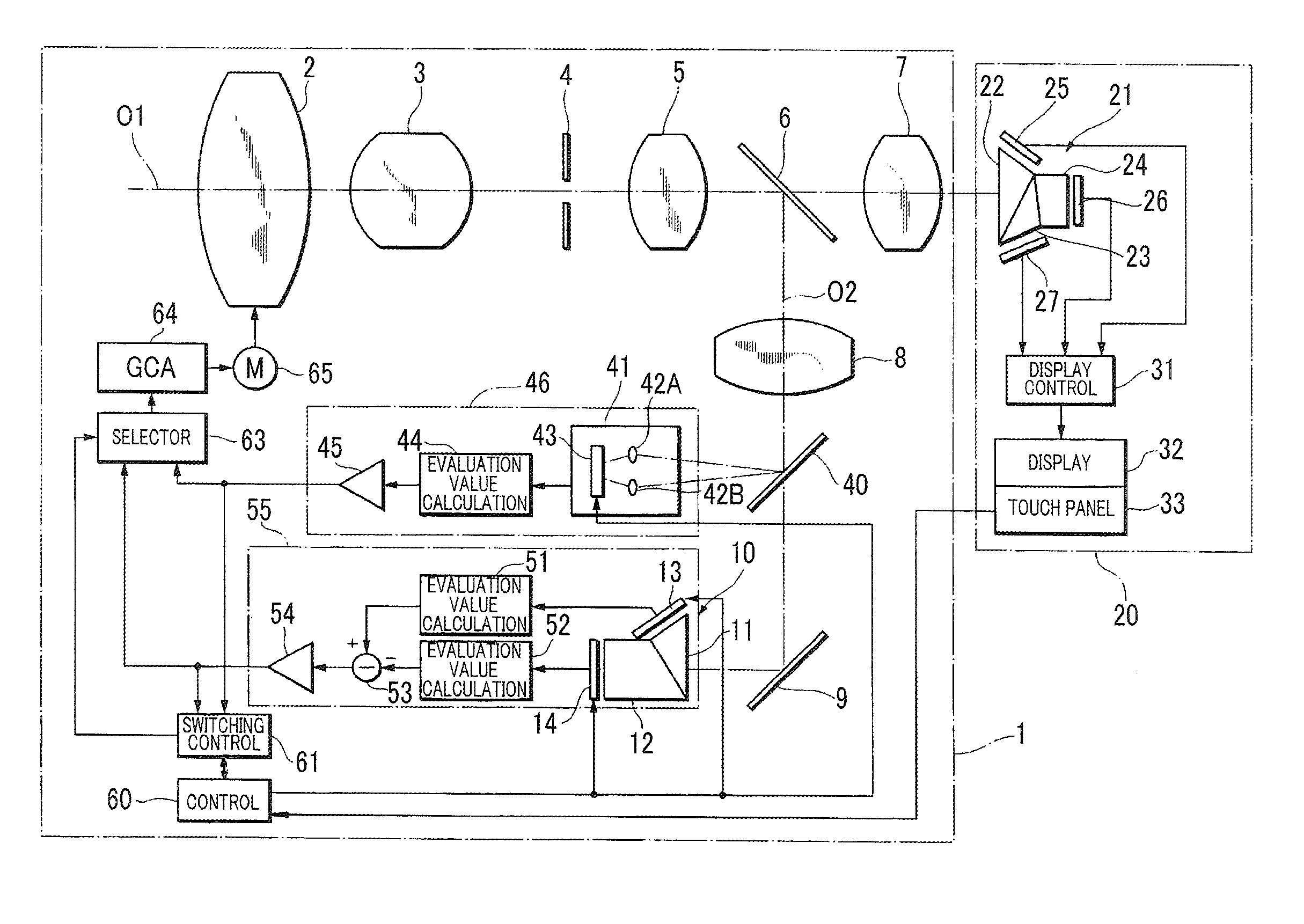
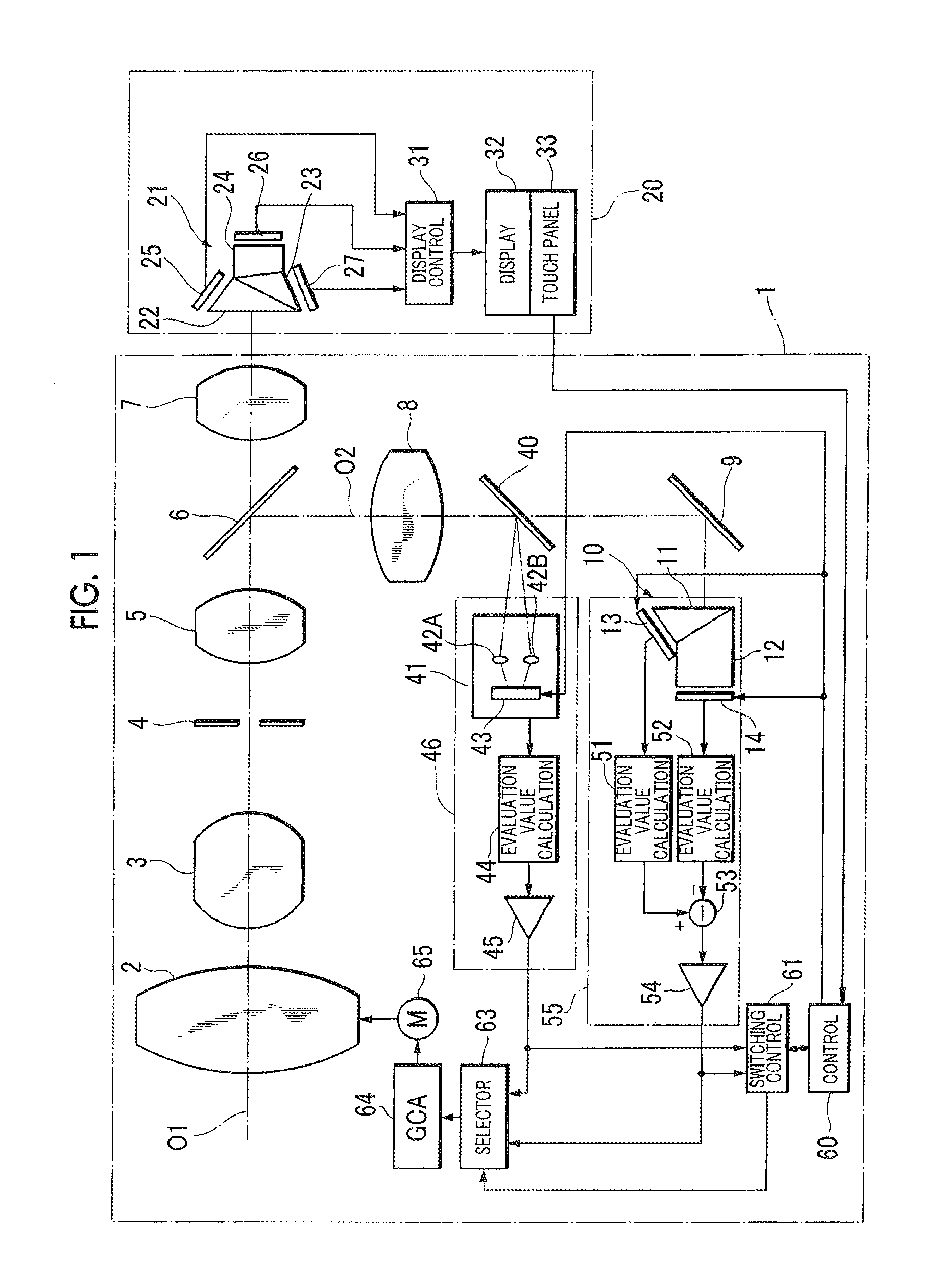
[0033]FIG. 1 shows an optical configuration of a part of a camera main body 20 and a photography lens unit 1 used for broadcast according to an example of the invention.

[0034]The photography lens unit 1 is detachably mounted on the camera main body 20.

[0035]The photography lens unit 1 includes a focus lens (focus lens group) 2, a zoom lens (zoom lens group) 3, a front relay lens (front relay lens group) 5, and a rear relay lens (rear relay lens group) 7 each of which has an optical axis which is the same as an optical axis O1 of the photography lens unit 1. A diaphragm 4 is disposed between the zoom lens 3 and the front relay lens 5 such that the optical axis O1 of the photography lens unit 1 passes through the center. Further, a half mirror 6 is disposed between the front relay lens 5 and the rear relay lens 7.

[0036]The camera main body 20 is provided with a color separation prism 21 that has an optical axis the same as the optical axis O1 of the photography lens unit 1 when the ph...


PUM


Abstract

This invention provides an auto-focus device, which is for eliminating an uncomfortable feeling when phase difference AF is switched to optical path length difference AF when an arbitrary area is set as a focusing target area, and a method for controlling operation of the same. A cameraman sets a desired area as the focusing target area. Until a focus lens reaches a first threshold value position, the focus lens is moved on the basis of a phase difference AF evaluation value obtained from a phase difference AF sensor so as to bring the center portion of the imaging area into focus. Until the focus lens reaches a second threshold value position, the focus lens is moved on the basis of a phase difference AF evaluation value which is output from a phase difference imaging element and is obtained from a signal of an area corresponding to the set focusing target area. When the focus lens reaches the second threshold value position, the focus lens is positioned at the focusing position using the differential AF evaluation value, which is obtained on the basis of the set focusing target area, among the differential AF evaluation values obtained from an optical path length difference AF sensor.

Description

CROSS-REFERENCE TO RELATED APPLICATIONS[0001]This application is a Continuation of PCT International Application No. PCT / JP2014 / 063775 filed on May 26, 2014, which claims priority under 35 U.S.C. §119(a) to Japanese Patent Application No. 2013-119413 filed Jun. 6, 2013. Each of the above application(s) is hereby expressly incorporated by reference, in its entirety, into the present application.BACKGROUND OF THE INVENTION[0002]1. Field of the Invention[0003]The invention relates to an auto-focus device and a method for controlling operation of the same.[0004]2. Description of the Related Art[0005]Examples of auto-focus modes of a camera include phase difference AF (auto-focus) and contrast AF. In the phase difference AF, light incident from a lens is divided into two or three or more rays through a pupil division, and is guided into a phase difference AF sensor, and a focusing direction and an amount of defocus are determined on the basis of an amount of position shift or a position ...

Claims


Application Information

Patent Timeline
IPC IPC(8): H04N5/232G02B7/09H04N5/225
CPCH04N5/23212H04N5/23293G02B7/09H04N5/232H04N5/23245H04N5/2254G02B7/36G02B7/38G03B13/36G02B7/282G02B7/343H04N23/672H04N23/55H04N23/61H04N23/62H04N23/611H04N23/632H04N23/635H04N23/667
Inventor EBATO, TAKASHISATO, TAKAHISASEKIYA, AIKO
Owner FUJIFILM CORP
Why Eureka
Try Eureka