Brake system

Inactive Publication Date: 2008-10-02
HONDA MOTOR CO LTD
View PDF12 Cites 7 Cited by
  • Summary
  • Abstract
  • Description
  • Claims
  • Application Information

AI Technical Summary

Benefits of technology

[0012]With the second aspect of the present invention, the first sensor, which activates the brake light based on a timing at which the slave cylinder generates brake fluid pressure when the slave cylinder operates normally, also serves as a sensor that generates an electrical signal responsive to the operating amount of the brake pedal by the driver in order to operate the slave cylinder. Therefore, it is possible to reduce the number of sensors required by the system.
[0014]With the third aspect of the present invention, when braking is performed by the brake fluid pressure generated by the slave cylinder which is operated based on an electrical signal responsive to the braking operation by the driver, the first fluid pressure sensor detects the brake fluid pressure generated by the master cylinder, the second fluid sensor detects the brake fluid pressure generated by the slave cylinder, and the slave cylinder generates brake fluid pressure such that the brake fluid pressure detected by the second fluid pressure sensor is adjusted to a level corresponding to the brake fluid pressure detected by the first fluid pressure sensor. Therefore, it is possible to cause the slave cylinder to generate brake fluid pressure corresponding to the operational amount of the master cylinder, thereby providing a braking force required by the driver.
[0016]With the fourth aspect of the present invention, the stroke simulator is connected to the master cylinder through the reaction force permission valve, and the brake fluid pressure generated by the master cylinder is absorbed by the stroke simulator when the reaction force permission valve is opened during normal system operation. Therefore, it is possible to provide a pedal feeling equivalent to that provided when braking by the brake fluid pressure generated by the master cylinder, thereby eliminating any possibility that the driver may experience an uncomfortable feeling. Further, because the brake fluid pressure generated by the master cylinder is supplied to the wheel cylinder without being absorbed by the stroke simulator when the reaction force permission valve is closed during abnormal system operation, it is possible to perform braking by the brake fluid pressure generated by the master cylinder without any problem even when the slave cylinder becomes inoperative.

Problems solved by technology

This is because, if the above-described order is reversed, the brake fluid pressure generated by the master cylinder is transmitted to the wheel cylinder through the fluid pressure chamber of the slave cylinder before the driver sufficiently depresses the brake pedal and the slave cylinder generates brake fluid pressure, resulting in an undesirable situation in which the thus-transmitted brake fluid pressure of the master cylinder affects the control of the brake fluid pressure by the slave cylinder.
However, in the conventional BBW brake system, the wheel cylinder is operated by the brake fluid pressure generated by the slave cylinder during normal system operation and the wheel cylinder is operated by the brake fluid pressure generated by the master cylinder during abnormal system operation.
Therefore, if the brake light is set so as to light up at the timing at which the slave cylinder generates brake fluid pressure during normal system operation, a delay occurs in the timing at which the brake light lights up during abnormal system operation where braking is performed by the brake fluid pressure generated by the master cylinder.
Conversely, if the brake light is set so as to light up at a timing at which the master cylinder generates brake fluid pressure during abnormal system operation, the brake light lights up too early during normal system operation where braking is performed by the brake fluid pressure generated by the slave cylinder.

Method used


Image

  • Brake system
  • Brake system
  • Brake system

Examples


Embodiment Construction

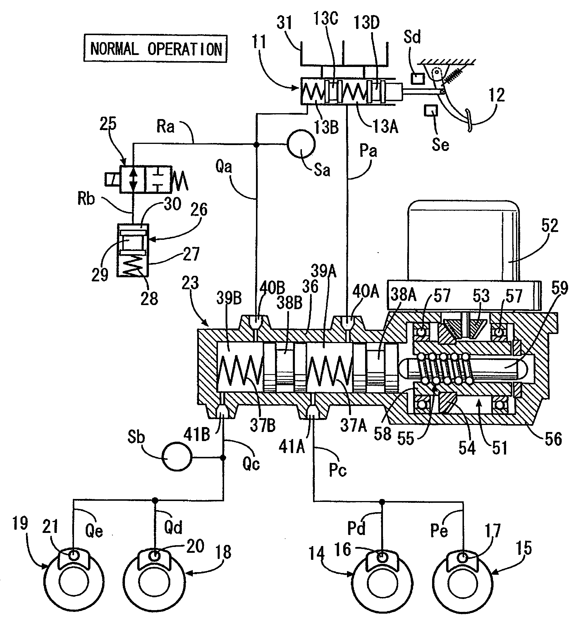
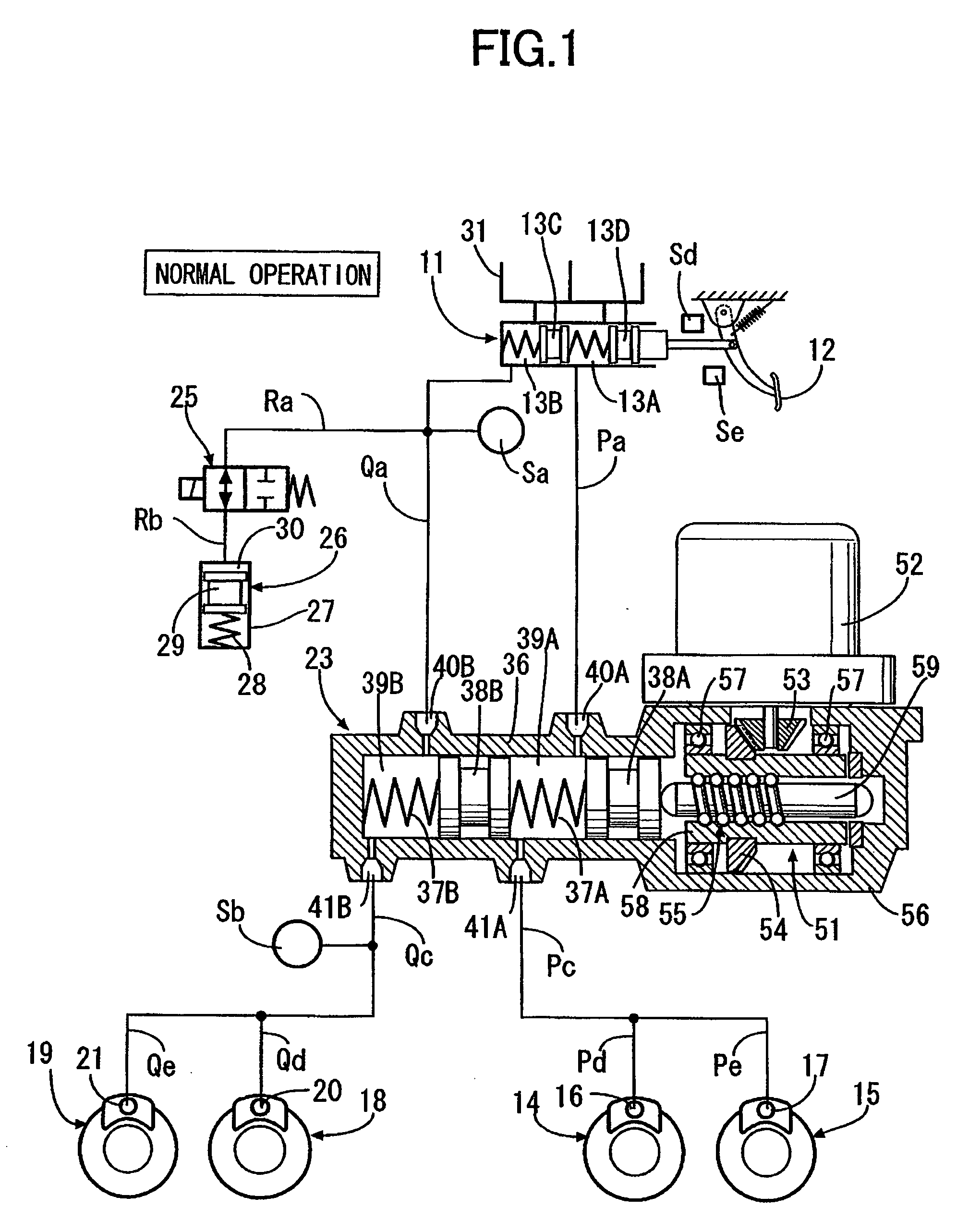
[0025]As shown in FIG. 1, a tandem master cylinder 11 has two first fluid pressure chambers 13A and 13B which output brake fluid pressure according to a pushing force applied to a brake pedal 12 by a driver depressing the brake pedal 12. One of the first fluid pressure chambers 13A is connected to wheel cylinders 16 and 17 of disc brake devices 14 and 15 for braking, for example, a left front wheel and a right rear wheel, through fluid passages Pa, Pc, Pd, and Pe. The other first fluid pressure chamber 13B is connected to wheel cylinders 20 and 21 of disc brake devices 18 and 19 for braking, for example, a right front wheel and a left rear wheel through fluid passages Qa, Qc, Qd, and Qe.

[0026]A slave cylinder 23 is provided between the fluid passages Pa, Qa and the fluid passages Pc, Qc. A stroke simulator 26 is connected to the fluid passages Ra and Rb branching from the fluid passage Qa via a reaction force permission valve 25 which is a normally closed solenoid valve. The stroke ...


PUM


Abstract

A brake system includes a master cylinder which generates brake fluid pressure by a braking operation of a driver, an electric motor driven slave cylinder that generates brake fluid pressure according to an electrical signal based on the braking operation of the driver, a vehicle wheel cylinder for braking a wheel by the brake fluid pressure generated in the master cylinder or the slave cylinder, a brake light that informs a following vehicle of the operation of the wheel cylinder, and a first sensor and a second sensor that detect stroke positions of the brake pedal. During normal operation of the brake system the brake fluid pressure generated in the slave cylinder is transferred to the wheel cylinder. During abnormal operation of the brake system, the brake fluid pressure generated in the master cylinder is transferred to the wheel cylinder. Further, the first sensor activates the brake light when the slave cylinder operates normally, and the second sensor activates the brake light when the slave cylinder does not operate normally.

Description

CROSS REFERENCE TO RELATED APPLICATIONS[0001]The present invention claims priority under 35 USC §119 based on Japanese patent application No. 2007-81220 filed 27 Mar. 2007. The subject matter of this priority document is incorporated by reference herein.BACKGROUND OF THE INVENTION [0002]1. Field of the Invention[0003]The present invention relates to a brake system comprising a master cylinder that generates brake fluid pressure by a braking operation of a driver, and an electric motor-driven slave cylinder that generates brake fluid pressure according to an electrical signal based on the braking operation of the driver.[0004]2. Description of the Related Art[0005]Japanese Patent Application Laid-open No. 2006-306221 discloses a brake system of the type referred to as a brake-by-wire (BBW) brake system, which converts a braking operation of a driver into an electrical signal used to operate an electric brake force generator or generating means, such as a slave cylinder, and operates ...

Claims


Application Information

Patent Timeline
IPC IPC(8): B60T13/12
CPCB60Q1/44B60T7/042B60T8/4081
Inventor HATANO, KUNIMICHI
Owner HONDA MOTOR CO LTD
Why Eureka
Try Eureka