Image display device, image display method and image display program

a technology of image display and image display device, which is applied in the direction of material analysis using wave/particle radiation, applications, instruments, etc., can solve the problems of difficult to perform a process in real time and take a long time to perform a detection operation, and achieve the effect of easy positioning and high efficiency

Active Publication Date: 2016-04-07
FUJIFILM CORP
View PDF2 Cites 18 Cited by
  • Summary
  • Abstract
  • Description
  • Claims
  • Application Information

AI Technical Summary

Benefits of technology

[0012]The invention has been made in view of the above-mentioned problems and an object of the invention is to provide a technique which can rapidly display a tomographic image corresponding to a designated position when image diagnosis is performed with reference to both a two-dimensional radiological image and a tomographic image.
[0032]According to the invention, when at least one of a two-dimensional radiological image and a plurality of tomographic images of the same subject is displayed, a depth map in which each position on the two-dimensional radiological image is associated with depth information indicating a position of a tomographic plane corresponding to each position in a depth direction is created. Therefore, when image diagnosis is performed with reference to both the two-dimensional radiological image and the tomographic images, first, it is possible to easily designate the position of a lesion with reference to the two-dimensional radiological image. In addition, it is possible to rapidly specify the tomographic image of the tomographic plane corresponding to the designated position of the lesion, with reference to the depth map. Therefore, it is possible to rapidly display a specified tomographic image together with the two-dimensional radiological image. As a result, it is possible to perform image diagnosis with high efficiency, with reference to both the two-dimensional radiological image and the tomographic images.

Problems solved by technology

Therefore, it takes a long time to perform an operation of detecting and displaying the tomographic image and it is difficult to perform a process in real time.

Method used


Image

  • Image display device, image display method and image display program
  • Image display device, image display method and image display program
  • Image display device, image display method and image display program

Examples


first embodiment

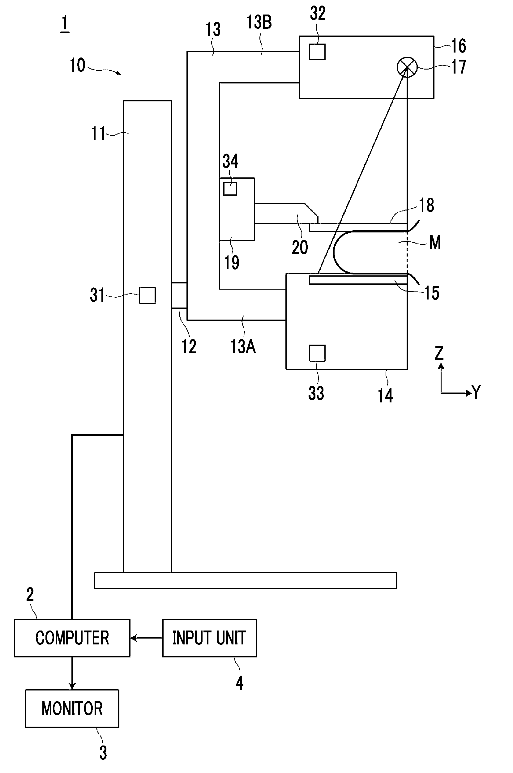
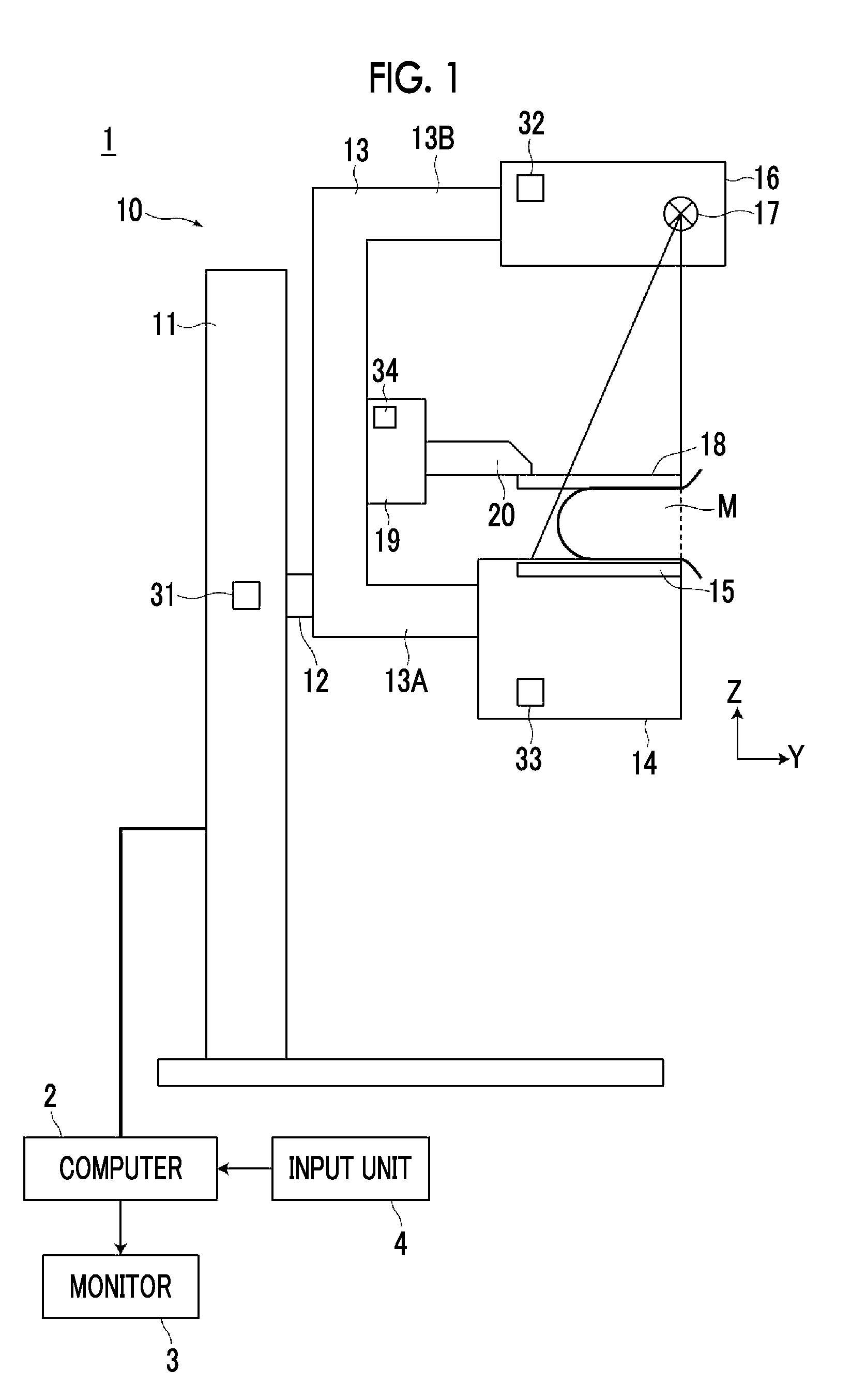
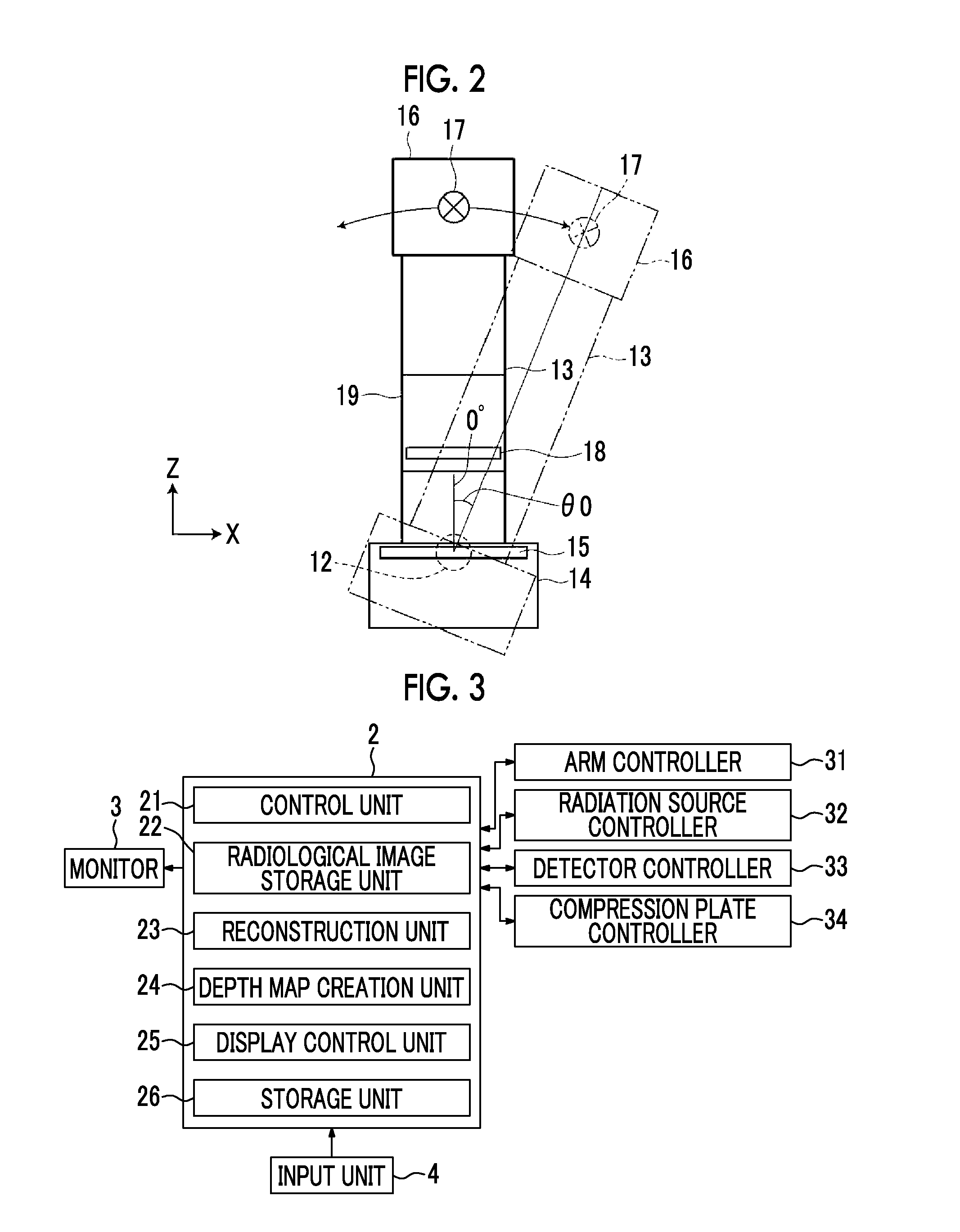
[0053]Hereinafter, embodiments of the invention will be described with reference to the drawings. FIG. 1 is a diagram schematically illustrating the structure of a radiography apparatus to which an image display device according to the invention is applied. A radiography apparatus 1 is a mammography apparatus which captures the images of the breast M in different imaging directions to acquire a plurality of radiological images in order to generate a two-dimensional radiological image using simple mammography and to generate a tomographic image using breast tomosynthesis imaging. As illustrated in FIG. 1, the radiography apparatus 1 includes an imaging unit 10, a computer 2 connected to the imaging unit 10, and a monitor 3 and an input unit 4 which are connected to the computer 2.

[0054]The imaging unit 10 includes a base 11, a rotating shaft 12 which is movable in the vertical direction (Z direction) with respect to the base 11 and is rotatable, and an arm unit 13 which is connected ...

second embodiment

[0090]In the above-described embodiment, the two-dimensional radiological image G0 and the tomographic image Di are acquired at the same time. However, for example, in health examination, when the result of diagnosis using the two-dimensional radiological image G0 shows that thorough medical examination is required and a tomographic image is acquired by tomosynthesis imaging in the thorough medical examination, the two-dimensional radiological image G0 and the tomographic image Di are captured at different times. As a result, the geometric shape of the breast M included in the two-dimensional radiological image G0 is different from that of the breast M included in the tomographic image Di due to, for example, a difference in the degree of compression or a minute difference in the imaging position. In this case, the positional relationship between the two-dimensional radiological image G0 and the depth map MP varies. As a result, there is a concern that each position on the two-dimen...

third embodiment

[0100]In some cases, the following method is used in order to reduce the exposure dose of the subject or to shorten the imaging time: the two-dimensional radiological image G0 is not captured; a pseudo two-dimensional image, such as an MIP image, is generated from a tomographic image acquired by tomosynthesis imaging; and the pseudo two-dimensional image is used as the two-dimensional radiological image G0 for image diagnosis. However, in the tomosynthesis imaging, the emission angle of radiation is limited. Therefore, even when a projection image is simply superimposed by, for example, the back projection method to reconstruct the tomographic image, the virtual image of a structure is likely to be captured in an area in which no structure is inherently present. Specifically, in some cases, the image of an artifact is captured in the area in which no structure is originally present in the tomographic image of the tomographic plane that is different from the tomographic image of the ...


PUM


Abstract

When at least one of a two-dimensional radiological image and a plurality of tomographic images of the same subject is displayed on a monitor, a depth map creation unit creates a depth map in which each position on the pseudo two-dimensional image is associated with depth information indicating the position of a tomographic plane corresponding to each position in a depth direction. A display control unit specifies the depth information of a predetermined position in the two-dimensional radiological image, with reference to the depth map, and displays the tomographic image of the tomographic plane indicated by the specified depth information on the monitor.

Description

CROSS-REFERENCE TO RELATED APPLICATIONS[0001]This application is a Continuation of PCT International Application No. PCT / JP2014 / 003280 filed on Jun. 18, 2014, which claims priority under 35 U.S.C. §119 (a) to Japanese Patent Application No. 2013-130533 filed on Jun. 21, 2013. Each of the above applications is hereby expressly incorporated by reference, in its entirety, into the present application.BACKGROUND OF THE INVENTION[0002]1. Field of the Invention[0003]The present invention relates to an image display device and method which displays a two-dimensional radiological image acquired by simple imaging and a tomographic image acquired by tomography, such as tomosynthesis imaging, and a program that causes a computer to perform an image display method.[0004]2. Description of the Related Art[0005]A medical image, such as a radiological image, is displayed and image diagnosis is performed with reference to a two-dimensional radiological image acquired by simple imaging and a tomograp...

Claims


Application Information

Patent Timeline
Patent Type & Authority Applications(United States)
IPC IPC(8): A61B6/00A61B6/02
CPCA61B6/502A61B6/463A61B6/025A61B6/0414A61B6/461A61B6/464A61B6/465A61B6/5294A61B34/25A61B2034/2068G01N2223/419G06T11/003G06T7/50G06T7/55G06T7/97
Inventor FUKUDA, WATARUMORITA, JUNYA
Owner FUJIFILM CORP
Why Eureka
Try Eureka