Combination Expansion Joint Strip

Active Publication Date: 2016-04-07
BACKRTAPE INC
View PDF0 Cites 4 Cited by
  • Summary
  • Abstract
  • Description
  • Claims
  • Application Information

AI Technical Summary

Benefits of technology

[0023]In one embodiment, the Invention comprises a double sided adhesive tape, an elongate flexible and compressible member such as a cellular foam strip, hereafter referred to as a compressible strip, and removable adhesive resistant strips, referred to hereafter as liners, to prevent the adhesive from inconveniently sticking to unintended surfaces before use. The assembly of these elements is slit almost completely through so that by tearing out the upper portion it can be divided into a lower portion which remains between the stucco and the window to permanently separate them and to serve

Problems solved by technology

Such joints frequently suffer from water intrusion resulting in structure damage because inadequate methods and materials are used in order to save labor and material cost.
While effective code-compliant methods and materials are available, they are expensive and time consuming to install.
Mechanical removal is required for any stucco which has gotten into the groove between the casing bead and the widow frame, as the masking does not cover the groove.d) Sealant Backing: A compressible strip usually called backer rod is forced into the gap between the casing bead and the window frame to partially fill the gap and thereby reduce the amount of sealant needed to fill the gap, and to prevent adhesion of the sealant to a third rigid surface at the bottom of the gap, as such third surface adhesion would detrimentally affect the performance of the sealant in stretching and compressing with relative movement of th

Method used


Image

  • Combination Expansion Joint Strip
  • Combination Expansion Joint Strip
  • Combination Expansion Joint Strip

Examples


Example

DETAILED DESCRIPTION OF THE FIGURES

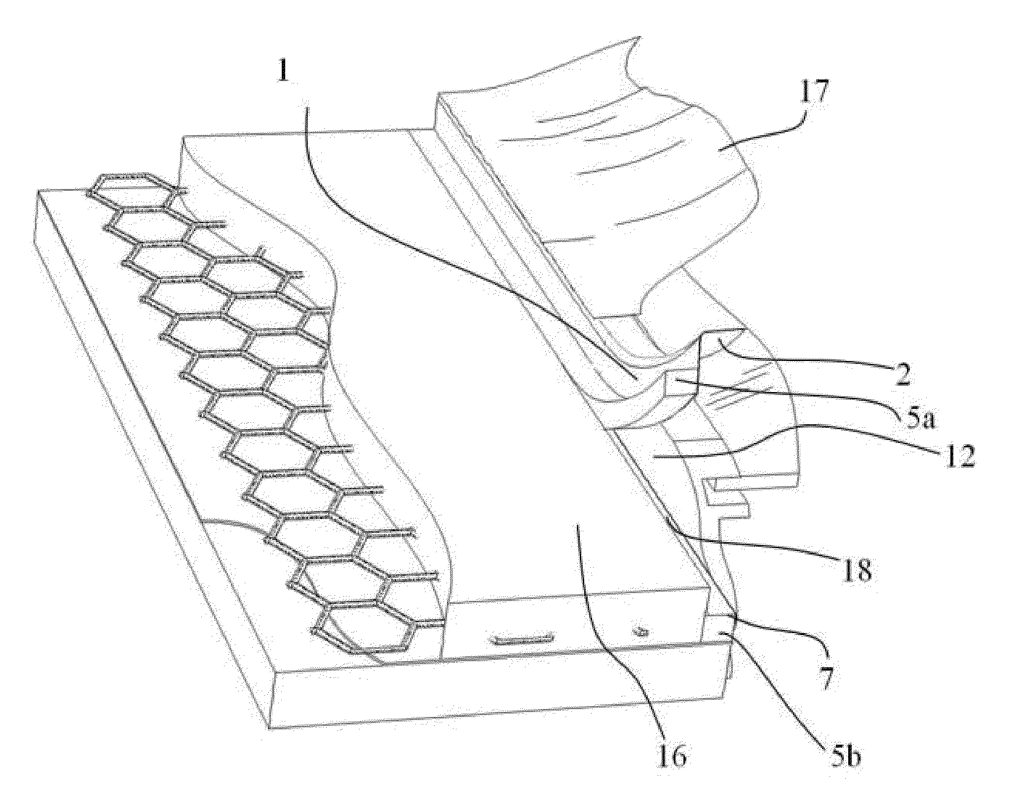
[0033]FIG. 1 shows an oblique end view of the layered construction of the Invention. A double sided Adhesive Tape Strip 1 is shown with a Front Surface 1a disposed to the left of the figure and an opposite Back Surface 1b disposed to the right of the figure. A Compressible Strip 5 is shown permanently adhered to Front Surface 1a substantially adjacent to the edge of Adhesive Tape Strip 1 closest to the bottom in FIG. 1. A Front Side Tape Liner 3, being an adhesive resistant material, is shown temporarily adhered to Front Surface 1a substantially covering the remaining portion of Front Surface 1a not covered by Compressible Strip 5 and, in this embodiment of the invention, is shown overhanging the upper edge of Adhesive Tape Strip 1, although such overhang is not a requirement of the invention. Front Side Tape Liner 3 is shown partially peeled back for clarity, but will normally remain adhered to Front Surface 1a until it is removed during use as sh...


PUM


Abstract

Provided is an improved multi-function expansion joint filler which combines the functions of building element spacer, surface finishing screed, masking attachment tape, sealant groove creation, and sealant groove backing material into a single strip for simplified sealing of building cladding joints, intersections or wall penetrations such as windows, doors, or other exterior facade penetration.

Description

REFERENCES CITED[0001]U.S. Pat. No. 6,418,688 Joint Forming Systems[0002]U.S. Pat. No. 4,023,324 Method for Making Expansion Joints for Roads and Buildings[0003]U.S. Pat. No. 3,807,107 Closure Spacer Member and Method of Erecting a Fixed Frame Assembly[0004]U.S. Pat. No. 6,993,874B2 Joint Materials and ConfigurationsCROSS-REFERENCE TO RELATED APPLICATIONS[0005]This application claims an invention which was disclosed in U.S. Provisional Application No. 62 / 059,635, filed 3 Oct. 2014, entitled “Combination Expansion Joint Strip with Strippable Screed Spacer, Masking Attachment, and Sealant Joint Backing Material”. The benefit under 35 USC §119(e) of the United States provisional application is hereby claimed, and the aforementioned application is hereby incorporated herein by reference.STATEMENT REGARDING FEDERALLY SPONSORED RESEARCH OR DEVELOPMENT[0006]Not ApplicableREFERENCE TO SEQUENCE LISTING, A TABLE, OR A COMPUTER PROGRAM LISTING COMPACT DISK APPENDIX[0007]Not ApplicableBACKGROUN...

Claims


Application Information

Patent Timeline
IPC IPC(8): E04F13/06
CPCE04F13/06E04F2013/063E06B1/62E06B2001/622E04G21/30
Inventor RODLER, MICAH
Owner BACKRTAPE INC
Why Eureka
Try Eureka