Vibration plate for a music box

a technology for vibration plates and music boxes, applied in the field of vibration plates, can solve the problems of not being able to achieve optimal results, and achieve the effects of reducing wear and deformation of strips, simple design, and reducing production costs

Active Publication Date: 2016-04-07
MONTRES BREGUET
View PDF0 Cites 1 Cited by
  • Summary
  • Abstract
  • Description
  • Claims
  • Application Information

AI Technical Summary

Benefits of technology

[0009]It is also an object of the invention, at least in one particular embodiment, to propose a vibration plate that can limit the wear and deformation of the strips.
[0010]It is also an object of the invention to provide a compact vibration plate.
[0011]Yet another object of the invention is to provide a vibration plate of simple design that is economical to manufacture.
[0013]As a result of these features, this bi-material vibration plate makes it possible to select a material that is suitable as a function of mechanical strength for the strips reproducing the sounds of a first frequency range, typically high pitched sounds, and on the other hand, to select a material suitable as a function of the required activation energy for the strips reproducing the sounds of a second frequency range, typically low pitched sounds. There is thus obtained a vibration plate which exhibits optimum performance for the reproduction of sounds over the desired frequency range or ranges of the vibration plate.
[0016]the second material has a Young's modulus of between 70 GPa and 120 GPa, a density of between 14000 kg / m3 and 20000 kg / m3, a hardness of less than 300 HV, and a tensile strength of less than 600 MPA, which makes it possible to have a material with higher activation energy;

Problems solved by technology

The vibration plates of current striking watches thus have a major drawback since a single material is used to manufacture the vibration plate strips, which means that manufacturers must make a compromise in the selection of material to make strips with acceptable vibration performance for both short strips and long strips.
Such a compromise cannot thus achieve optimum results for the reproduction of high and low pitched sounds.

Method used


Image

  • Vibration plate for a music box
  • Vibration plate for a music box
  • Vibration plate for a music box

Examples


Embodiment Construction

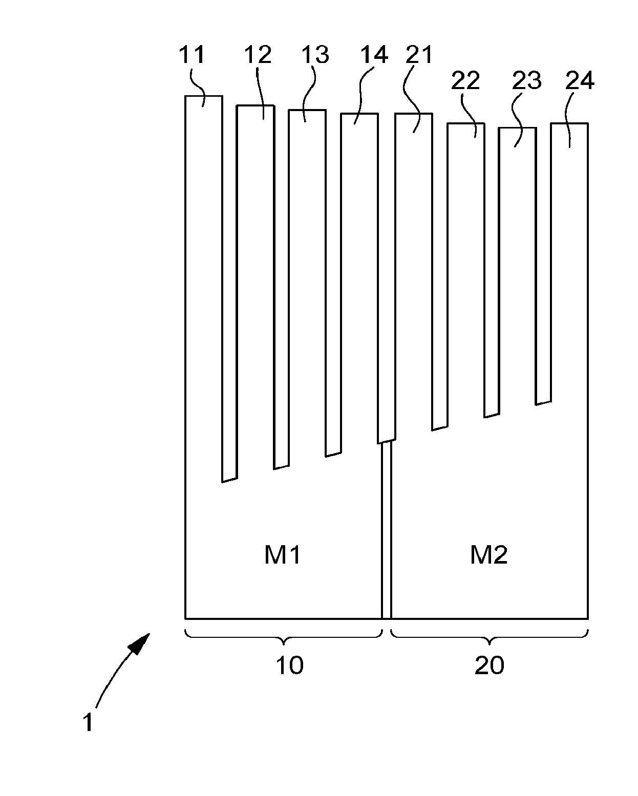
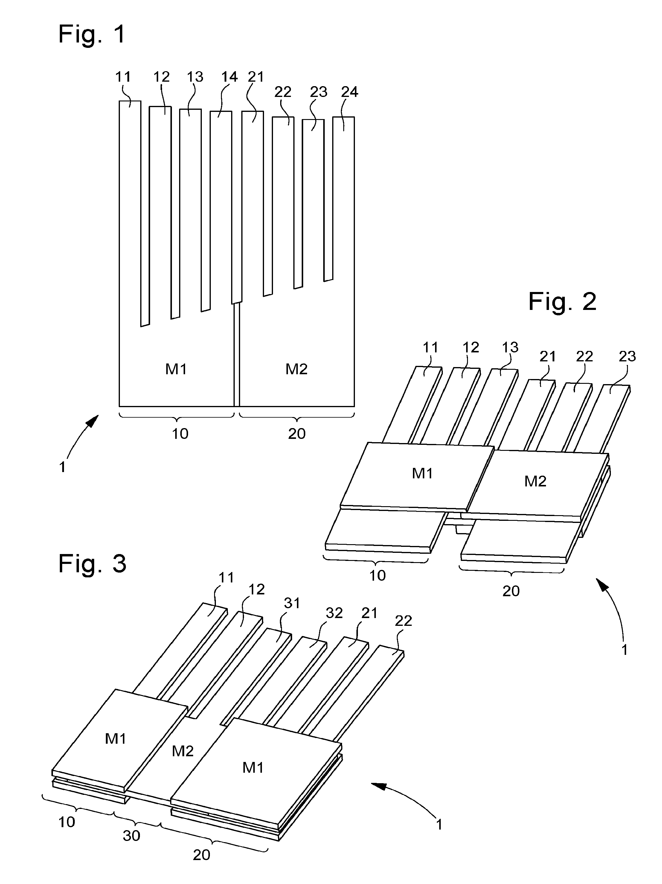
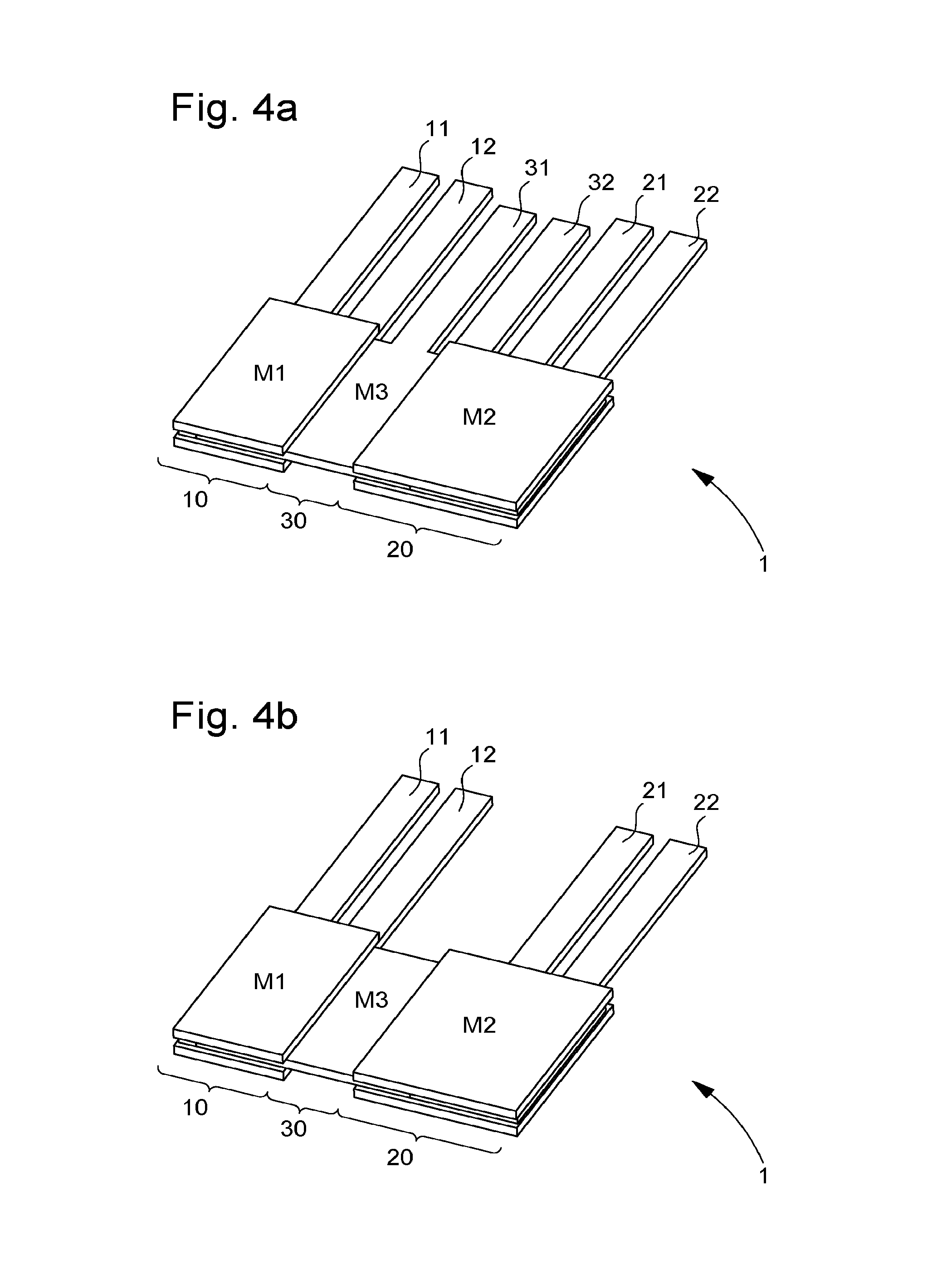
[0030]A vibration plate for a music box of small size will now be described below with reference jointly to FIGS. 1, 2, 3, 4a and 4b.

[0031]The invention concerns a vibration plate 1 including at least two parts, joined to each other, manufactured in at least two materials, a first part 10 forming a first set of strips 11, 12, 13, 14 made of a first material M1 so as to produce sounds in a first frequency range, and at least a second part 20 forming a second set of strips 21, 22, 23, 24 made of a second material M2 so as to produce sounds in a second frequency range.

[0032]The first frequency range may, for example, extend from 1600 Hz to 20 kHz, which makes it possible to reproduce high pitched sounds. The second frequency range may extend from 20 Hz to 400 Hz which makes it possible to reproduce low pitched sounds. It is also possible to consider the frequency range extending from 400 Hz to 1600 Hz in order to reproduce medium pitched sounds.

[0033]According to the invention, the fi...


PUM


Abstract

The invention relates to a vibration plate for a striking mechanism of musical watches or music boxes. According to the invention, the vibration plate includes at least two parts, joined to each other, manufactured in at least two materials, a first part forming a first set of strips made of a first material so as to produce sounds in a first frequency range, and at least a second part forming a second set of strips made of a second material so as to produce sounds in a second frequency range.

Description

[0001]This application claims priority from European Patent Application No. 14187634.2 filed on Oct. 3, 2014, the entire disclosure of which is hereby incorporated herein by reference.FIELD OF THE INVENTION[0002]The invention relates to the field of musical watches and music boxes of small dimensions.BACKGROUND OF THE INVENTION[0003]Generally, the striking mechanism of music boxes is formed by a vibration plate provided with several strips and a system of activating the strips of the vibration plate; the activation system may take the form of a rotating cylinder or a rotating disc. To fit a watch with such a striking mechanism, it is necessary to reduce the size of the components while taking into account their mechanical strength and while retaining a good sound quality.[0004]Currently, the material of the vibration plate is selected mainly on the basis of manufacturability and resistance to wear and fatigue. Indeed, the strips of the vibration plate are subjected to repeated elast...

Claims


Application Information

Patent Timeline
Patent Type & Authority Applications(United States)
IPC IPC(8): G10K1/10
CPCG10D1/06G10K1/10G10F1/06G10F5/00G04B21/08G04B23/028
Inventor KARAPATIS, POLYCHRONIS NAKISKADMIRI, YOUNESSARCHI, DAVIDE
Owner MONTRES BREGUET
Why Eureka
Try Eureka