
Vehicle side airbag device

Inactive Publication Date: 2016-04-14
TOYOTA JIDOSHA KK
View PDF7 Cites 18 Cited by
  • Summary
  • Abstract
  • Description
  • Claims
  • Application Information

AI Technical Summary

Benefits of technology

The patent provides a vehicle side airbag device that improves head protection. This means that this device can better protect a person's head in the event of a collision, reducing the chances of injury.

Problems solved by technology

However, the structure of the side airbag device described above is such that the airbag bag body is set with a large vehicle up-down direction dimension, and an upper portion of the airbag bag body that protects the head of an occupant is not directly fixed to a seatback.
Therefore, in cases in which a flow of gas ejected into the airbag bag body from the inflator is not well controlled, there is a possibility of the upper portion of the airbag bag body swaying greatly during inflation and deployment.

Method used


Image

  • Vehicle side airbag device
  • Vehicle side airbag device
  • Vehicle side airbag device

Examples


second exemplary embodiment

[0066]FIG. 4 is a side view illustrating the airbag 20 in the inflated and deployed state in a vehicle side airbag device 60 according to a second exemplary embodiment. Note that illustration of the outer peripheral stitch section 34 is not illustrated in FIG. 4. In the present exemplary embodiment, an intermediate communication opening 62 is provided at an up-down direction intermediate portion of the partitioning section 24. The intermediate communication opening 62 is formed by partially omitting the stitched section 46 at an up-down direction intermediate portion of the upright extension portion 46B.

[0067]In the present exemplary embodiment, the upper end portion 28A of the diffuser 28 is formed with an upper side opening 64 that places the interior of the diffuser 28 and the interior of the front bag section 36 (the interior of the head protection portion 36A) in communication with each other. An up-down direction intermediate portion of the diffuser 28 is formed with a pair of...

third exemplary embodiment

[0073]FIG. 5 is a side view illustrating the inflated and deployed state of the airbag 20 in a vehicle side airbag device 70 according to a third exemplary embodiment. Note that the outer peripheral stitch section 34 is not illustrated in FIG. 5. In the present exemplary embodiment, a tether 72, serving as a partitioning section, is provided at the airbag 20 instead of the partitioning section 24 according to the first exemplary embodiment. In the inflated and deployed state of the airbag 20, the tether 72 includes a crosswise extension portion 72A extending from the up-down direction intermediate portion in the vicinity of the rear end portion of the airbag 20 toward the front side of the seatback 14, and reaching the vicinity of the front-rear direction center portion of the airbag 20. An upright extension portion 72B extends from a front end portion of the crosswise extension portion 72A toward the lower end side of the airbag 20.

[0074]The tether 72 is configured by a pair of bas...


PUM


Abstract

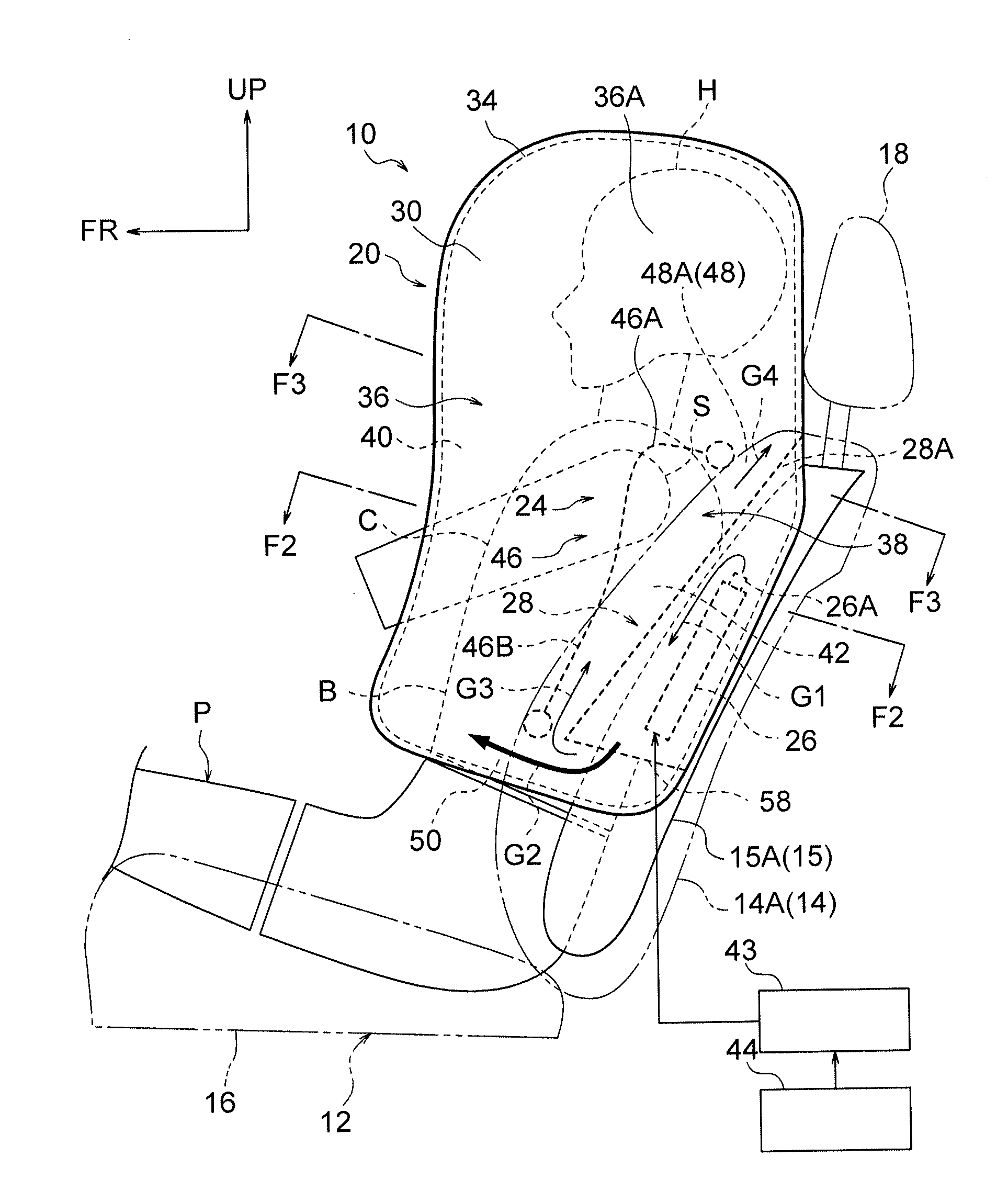
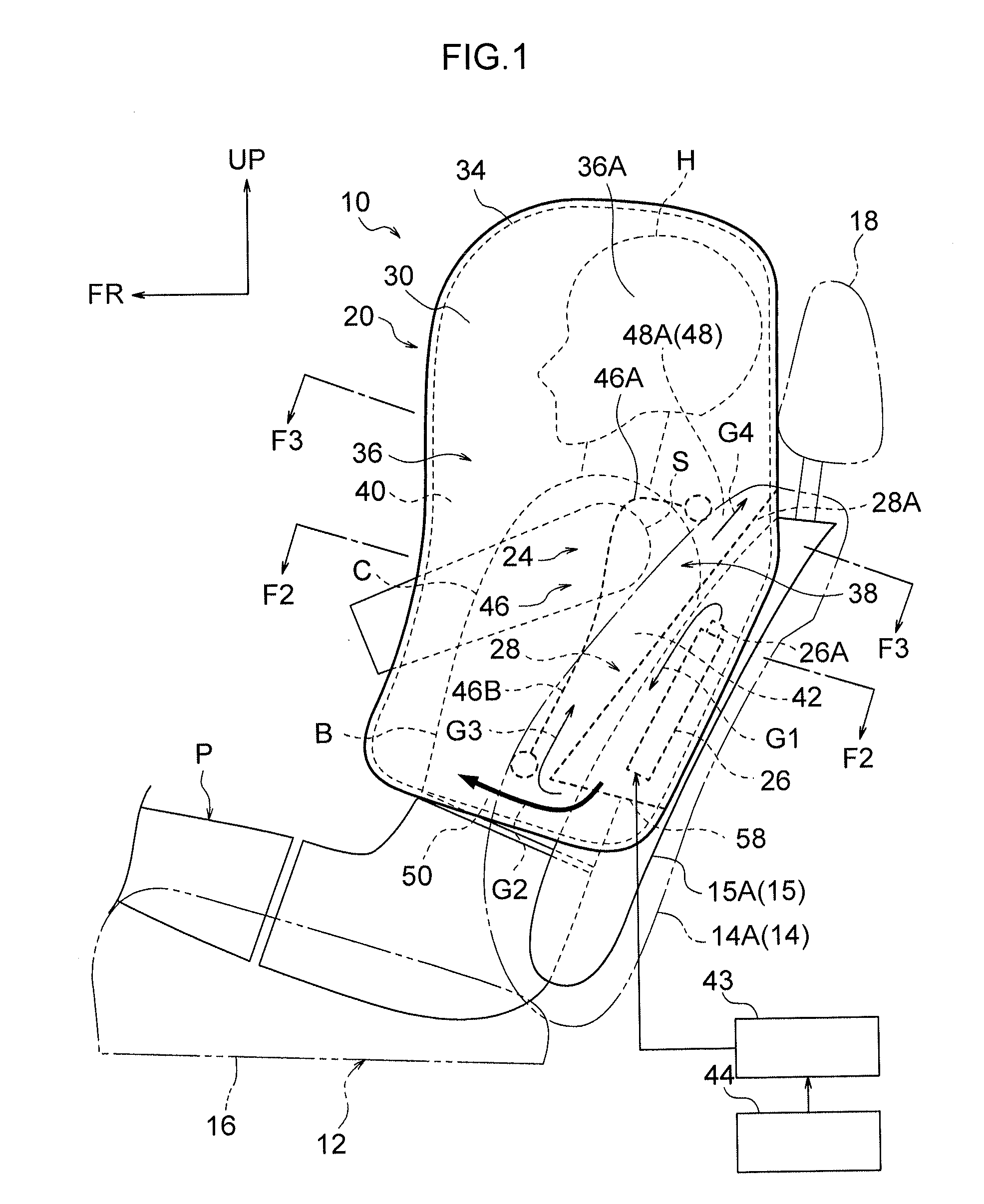
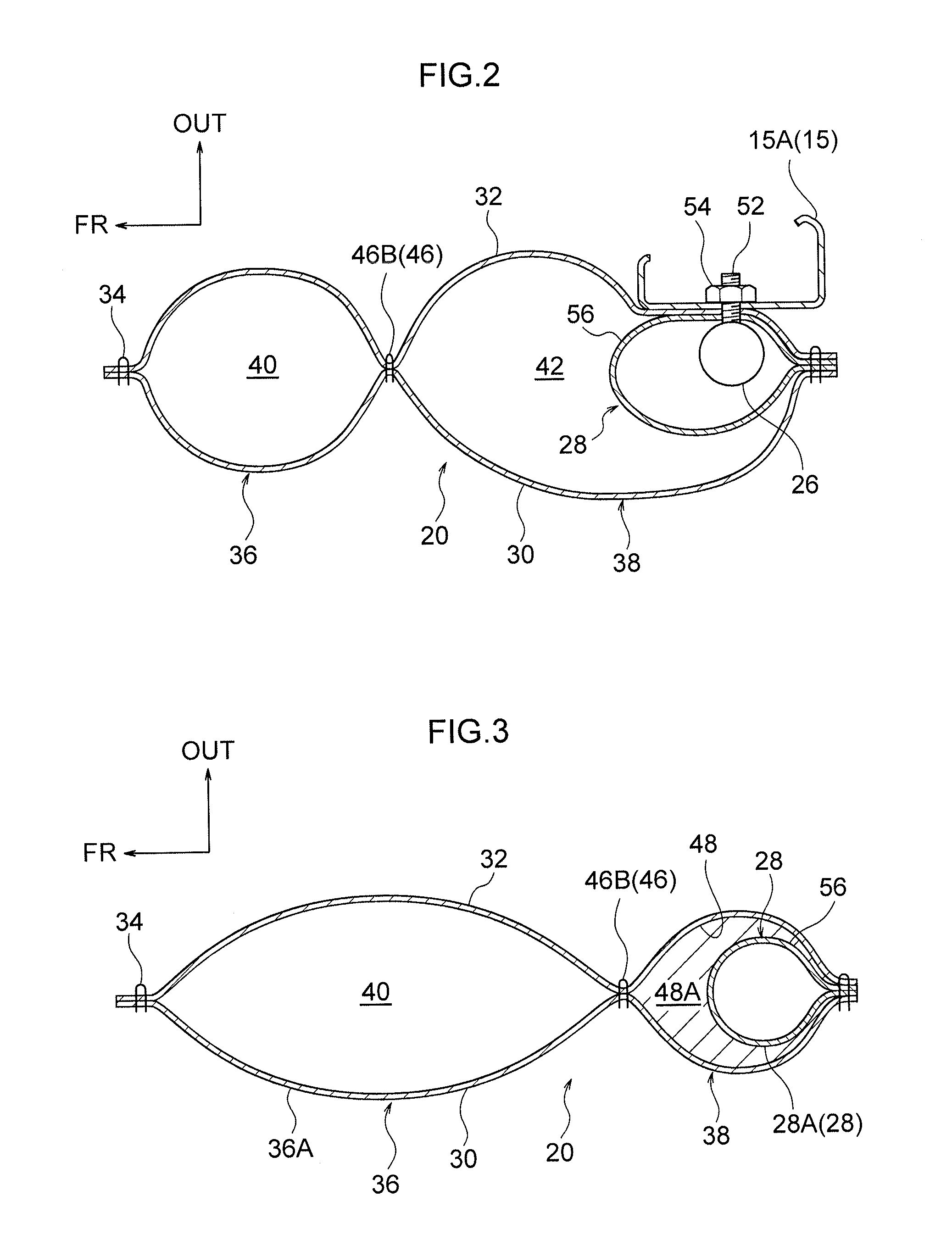
A vehicle side airbag device including: an inflator disposed at a side section of a seatback of a vehicle seat; a rear bag section that inflates and deploys using gas from the inflator housed therein; a front bag section into which gas is supplied through communication openings formed at a partitioning section between the front and rear bag sections, that inflates and deploys toward a vehicle front and upper side of the rear bag section, and that protects a head of an occupant at a vehicle upper side than the rear bag section; and a diffuser that is disposed inside the rear bag section, that houses the inflator and inflates using gas therefrom, wherein an upper end portion of the diffuser, where inflates, pierces through an upper communication opening that is one of the communication openings formed at an upper end portion of the partitioning section.

Description

CROSS-REFERENCE TO RELATED APPLICATION[0001]This application is based on and claims priority under 35 USC 119 from Japanese Patent Application No. 2014-209128 filed on Oct. 10, 2014, the disclosure of which is incorporated by reference herein.BACKGROUND[0002]1. Technical Field[0003]The present disclosure relates to a vehicle side airbag device.[0004]2. Related Art[0005]In an airbag device (side airbag device) described in Japanese Patent Application Laid-Open (JP-A) No. 2012-051557, an airbag bag body includes an inflation location that inflates on receipt of gas supplied from an inflator, and a non-inflation location. An opening is formed at the non-inflation location, and a tether inserted through the opening connects a rear end portion and a front end portion of the airbag bag body. A deployment trajectory of the airbag bag body is controlled by the tether.[0006]However, the structure of the side airbag device described above is such that the airbag bag body is set with a large v...

Claims


Application Information

Patent Timeline
IPC IPC(8): B60R21/231B60R21/2334B60R21/233B60R21/207
CPCB60R21/23138B60R21/207B60R2021/23324B60R21/233B60R2021/23146B60R21/2334B60R21/2346
Inventor FUJIWARA, YUSUKE
Owner TOYOTA JIDOSHA KK
Learn More