

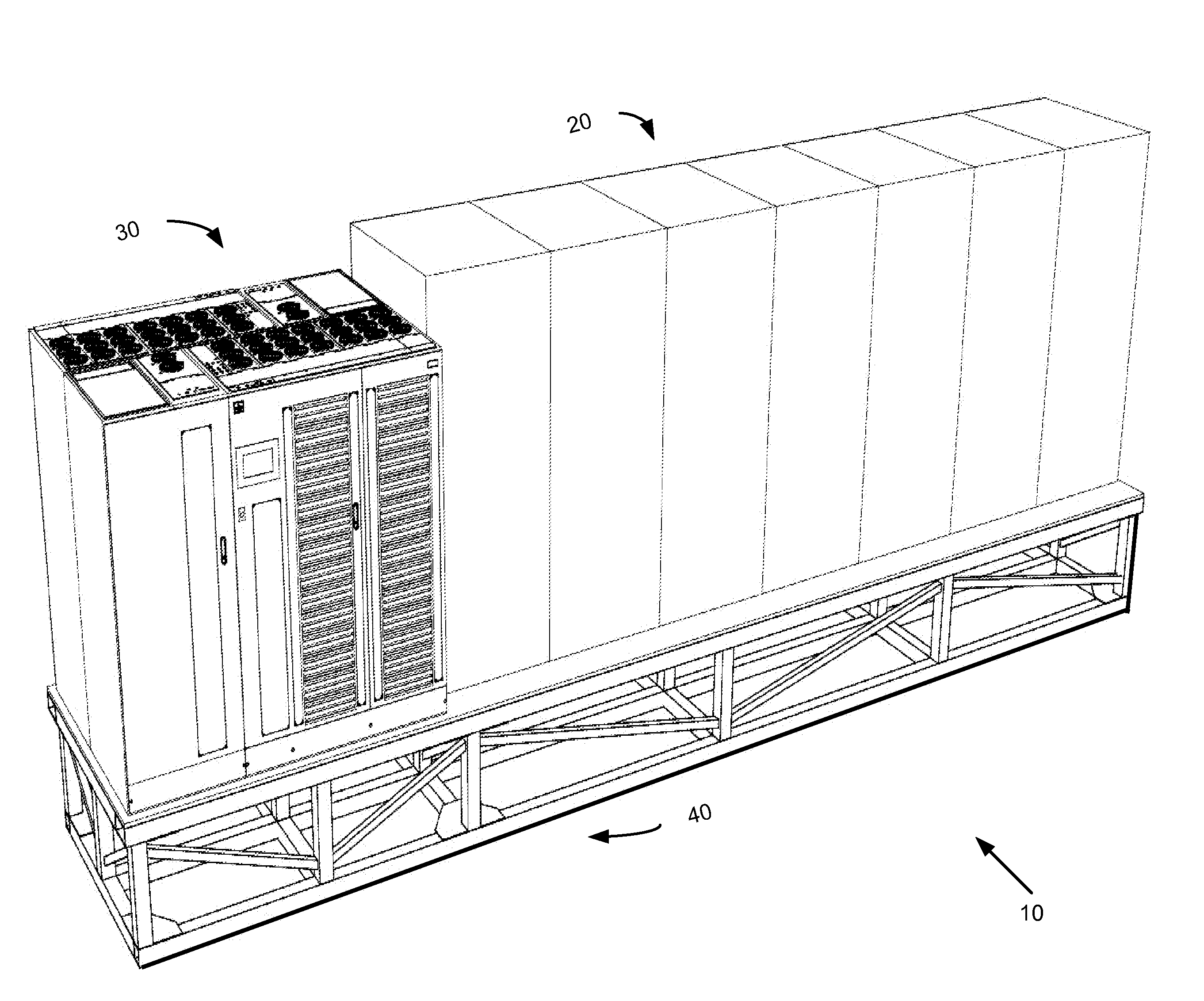
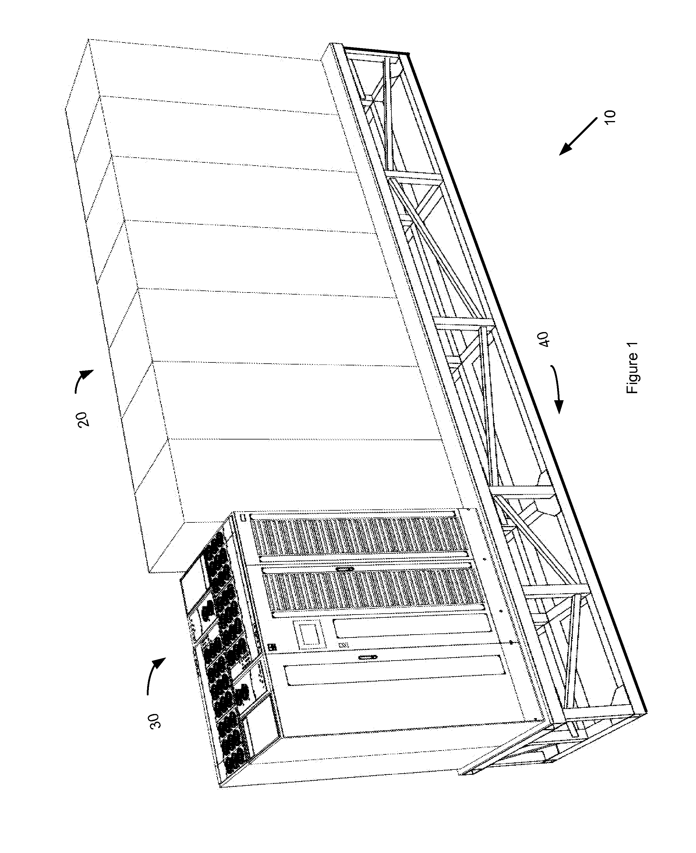
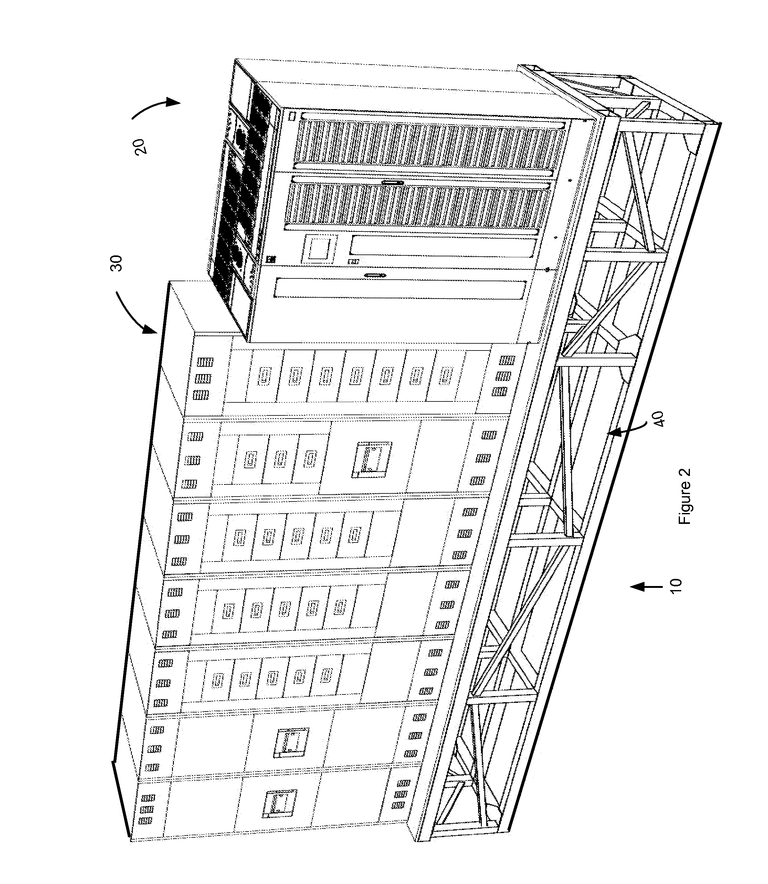
Modular Power Skid Assembled with Different Electrical Cabinets and Components Mounted on the Skid
a modular power skid and modular technology, applied in the direction of electrical apparatus construction details, electrical apparatus casings/cabinets/drawers, instruments, etc., can solve the problems of lack of ability to create truly interconnected facilities, lack of weather resistance, and current shipping containers on their own
- Summary
- Abstract
- Description
- Claims
- Application Information
AI Technical Summary
Benefits of technology
Problems solved by technology
Method used
Image

Examples
Embodiment Construction
[0016]In the following description, numerous specific details are set forth, such as examples of specific data signals, named components, connections, number of circuit breakers in a cabinet, etc., in order to provide a thorough understanding of the present invention. It will be apparent, however, to one of ordinary skill in the art that the present invention may be practiced without these specific details. In other instances, well known components or methods have not been described in detail but rather in a block diagram in order to avoid unnecessarily obscuring the present invention. Further specific numeric references, such as first cabinet, may be made. However, the specific numeric reference should not be interpreted as a literal sequential order but rather interpreted as a first cabinet is different than a second cabinet. Thus, the specific details set forth are merely exemplary. The specific details may be varied from and still be contemplated to be within the spirit and scop...
PUM
| Property | Measurement | Unit |
|---|---|---|
| Weight | aaaaa | aaaaa |
Abstract
Description
Claims
Application Information