Modifying light of a multicore assembly to produce a plurality of viewing zones

a multicore assembly and light technology, applied in the field of virtual reality and augmented reality imaging and visualization systems, can solve the problems of difficult production of vr or ar technology that facilitates, difficult to produce other virtual or real-world imagery elements, and complex human visual perception systems

Active Publication Date: 2016-04-21
MAGIC LEAP INC
View PDF10 Cites 17 Cited by
  • Summary
  • Abstract
  • Description
  • Claims
  • Application Information

AI Technical Summary

Benefits of technology

[0021]In one embodiment, a system of displaying virtual content to a user, comprises an image-generating source to provide one or more frames of image data, a multicore assembly comprising a plurality of multicore fibers to project light associated with the one or more frames of image data, a multicore fiber of the plurality of multicore fibers emitting light in a wavefront, such that the multicore assembly produces an aggregate wavefront of the projected light, and a phase modulator to induce phase delays between the multicore fibers in a manner such that the aggregate wavefront emitted by the multicore assembly is varied, thereby varying a focal distance at which the user perceives the one or more frames of image data.
[0022]In another embodiment, a system for displaying virtual content to a user comprises an array of microprojectors to project light beams associated with one or more frames of image data to be presented to the user, wherein the microprojector is configurable to be movable relative to one or more microprojectors of the array of the microprojectors,a frame to house the array of microprojectors, a processor operatively coupled to the one or more microprojectors of the array of microprojectors to control one or more light beams transmitted from the one or more projectors in a manner such that the one or more light beams are modulated as a function of a position of the one or more microprojectors relative to the array of microprojectors, thereby enabling delivery of a lightfield image to the user.

Problems solved by technology

As it turns out, the human visual perception system is very complex, and producing a VR or AR technology that facilitates a comfortable, natural-feeling, rich presentation of virtual image elements amongst other virtual or real-world imagery elements is challenging.
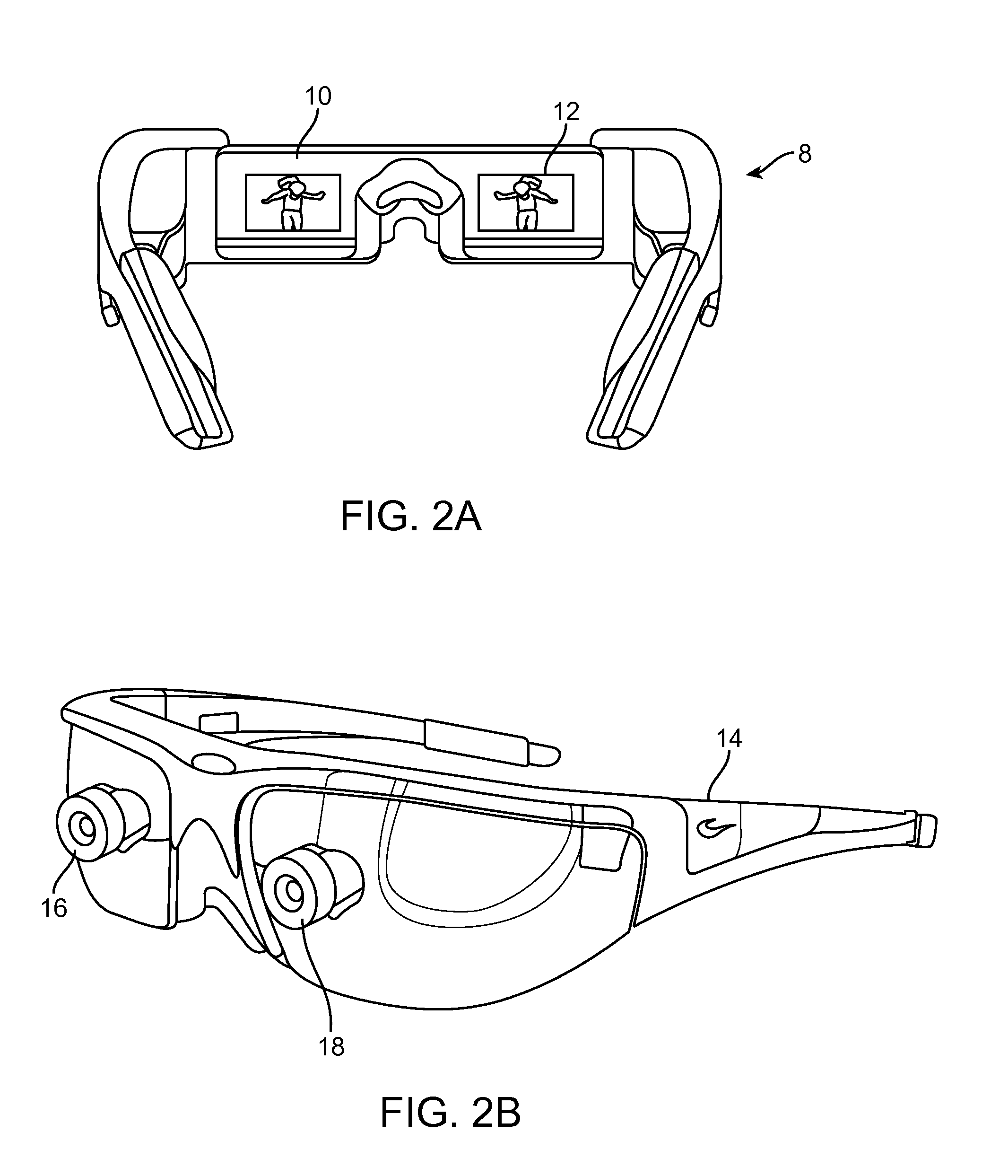
Such configurations have been found to be uncomfortable for many users due to a mismatch between vergence and accommodation which must be overcome to perceive the images in three dimensions; indeed, some users are not able to tolerate stereoscopic configurations. FIG. 2B shows another stereoscopic wearable glasses (14) type configuration featuring two forward-oriented cameras (16, 18) configured to capture images for an augmented reality presentation to the user through stereoscopic displays.
None of these configurations is optimally suited for presenting a rich, binocular, three-dimensional augmented reality experience in a manner that will be comfortable and maximally useful to the user, in part because prior systems fail to address some of the fundamental aspects of the human perception system, including the photoreceptors of the retina and their interoperation with the brain to produce the perception of visualization to the user.
In other words, without changes in stimulation, the photoreceptors do not provide input to the brain and blindness is experienced.
Working against this reflex, as do most conventional stereoscopic AR or VR configurations, is known to produce eye fatigue, headaches, or other forms of discomfort in users.
Further, most people prefer to move their heads when their eye gaze needs to move more than about 20 degrees off center to focus on a particular object (i.e., people do not typically like to look at things “from the corner of the eye”).

Method used


Image

  • Modifying light of a multicore assembly to produce a plurality of viewing zones
  • Modifying light of a multicore assembly to produce a plurality of viewing zones
  • Modifying light of a multicore assembly to produce a plurality of viewing zones

Examples


Embodiment Construction

[0046]Referring to FIGS. 4A-4D, some general componentry options are illustrated. In the portions of the detailed description which follow the discussion of FIGS. 4A-4D, various systems, subsystems, and components are presented for addressing the objectives of providing a high-quality, comfortably-perceived display system for human VR and / or AR.

[0047]As shown in FIG. 4A, an AR system user (60) is depicted wearing a frame (64) structure coupled to a display system (62) positioned in front of the eyes of the user. A speaker (66) is coupled to the frame (64) in the depicted configuration and positioned adjacent the ear canal of the user (in one embodiment, another speaker, not shown, is positioned adjacent the other ear canal of the user to provide for stereo / shapeable sound control). The display (62) is operatively coupled (68), such as by a wired lead or wireless connectivity, to a local processing and data module (70) which may be mounted in a variety of configurations, such as fixe...


PUM

PropertyMeasurementUnit
diameteraaaaaaaaaa
frequencyaaaaaaaaaa
distanceaaaaaaaaaa

Abstract

Configurations are disclosed for presenting virtual reality and augmented reality experiences to users. The system may comprise an image-generating source to provide one or more frames of image data in a time-sequential manner, a light modulator configured to transmit light associated with the one or more frames of image data, a substrate to direct image information to a user's eye, wherein the substrate houses a plurality of reflectors, a first reflector of the plurality of reflectors to reflect transmitted light associated with a first frame of image data at a first angle to the user's eye, and a second reflector to reflect transmitted light associated with a second frame of the image data at a second angle to the user's eye.

Description

CROSS-REFERENCE TO RELATED APPLICATIONS[0001]This application is a continuation of pending U.S. patent application Ser. No. 14 / 555,585, filed Nov. 27, 2014, entitled “VIRTUAL AND AUGMENTED REALITY SYSTEMS AND METHODS”, which claims priority from U.S. Provisional Application Ser. No. 61 / 909,774, filed Nov. 27, 2013, entitled “VIRTUAL AND AUGMENTED REALITY SYSTEMS AND METHODS”. The contents of the aforementioned applications are hereby expressly incorporated by reference into the present application their entireties.FIELD OF THE INVENTION[0002]The present disclosure relates to virtual reality and augmented reality imaging and visualization systems.BACKGROUND[0003]Modern computing and display technologies have facilitated the development of systems for so called “virtual reality” or “augmented reality” experiences, wherein digitally reproduced images or portions thereof are presented to a user in a manner wherein they seem to be, or may be perceived as, real. A virtual reality, or “VR”...

Claims


Application Information

Patent Timeline
Patent Type & Authority Applications(United States)
IPC IPC(8): G02B6/06G06T19/00G02B6/34G02B6/02G02B6/40
CPCG02B6/06G02B6/02042G02B6/40G02B6/34G06T19/006G02B2006/0098G02B27/017G02B27/0172G02B2027/014G02B2027/0138G02B2027/0178H04N13/239G06T7/73H04N13/363G06T7/50H04N13/117H04N13/286H04N13/341H04N13/344H04N13/361H04N13/366H04N13/383G02F1/0105G02F1/29G06T13/40G06T2213/08G02F1/292G02F1/31G02B2027/0125G02B27/4205G02F1/294G02B3/0006G02B3/0037G02B5/005G02B5/1814G02B5/1828G02B5/20G02B6/00G02B6/32G02B17/08G02B26/0808G02B27/0087G02B27/0093G02B27/01G02B27/0176G02B2027/0118G02B2027/0134G02B2027/0163G02F1/1334G02F1/17G06F3/011G06F3/013G06T5/003G06T15/10G06T15/506G06T19/20G06T2207/10021G06T2207/30201G09G5/003G09G5/02G09G5/10H04N5/21H04N5/74H04N2013/0085G06T17/10G06V40/193G06T15/00G02C2202/16G06V10/42G06F3/017G02B2027/0123G02C7/104G02C7/049G06T5/50G06F3/1423G06T5/002G06T19/003G09G5/18G02B30/24H04N23/00G02B30/34G06F3/012H04N13/327H04N13/332G02B2027/0187
Inventor SCHOWENGERDT, BRIAN T.
Owner MAGIC LEAP INC
Why Eureka
Try Eureka