
Method for measuring a distance of a component from an object and for setting a position of a component in a particle beam device

a technology of particle beam and component, which is applied in the direction of instruments, liquid/fluent solid measurement, engine lubrication, etc., can solve the problems of inability to reproduce the procedure, undesirable and disadvantageous, and the accuracy of the needle-shaped device is often difficult to measure, so as to achieve good particle detection, good deposition of material, and object distance

Active Publication Date: 2016-04-28
CARL ZEISS MICROSCOPY GMBH
View PDF0 Cites 7 Cited by
  • Summary
  • Abstract
  • Description
  • Claims
  • Application Information

AI Technical Summary

Benefits of technology

The patent describes a system for detecting and measuring the distance between an object and a component using a particle beam device. This system uses shadows created by interaction particles to determine the object distance. By approaching the object with the component, the shadow is reduced and the object distance can be observed. This allows for easy and quick positioning of the component to achieve the desired effect, such as good deposition of material onto a surface or good detection of particles. Overall, the system provides a simple and quick way for measuring the object distance and ensuring the desired positioning of the component.

Problems solved by technology

However, the accurate positioning of the needle-shaped device often presents problems.
Up until now, there has not been any reproducible procedure by which the needle-shaped device can always be arranged exactly at a specific position on the surface of the object.
Such a principle, however, is undesirable and disadvantageous.
On the one hand, positioning the needle-shaped device at a specific position can take quite a long time.
On the other hand, it is quite possible for errors to occur during the setting of the position, that is to say for there to be deviations from this position of the needle-shaped device, so that the needle-shaped device is not aligned sufficiently well with the position of the surface of the object.
This leads for example to a sparse and / or unreproducible deposition of a layer on the surface of the object.

Method used


Image

  • Method for measuring a distance of a component from an object and for setting a position of a component in a particle beam device
  • Method for measuring a distance of a component from an object and for setting a position of a component in a particle beam device
  • Method for measuring a distance of a component from an object and for setting a position of a component in a particle beam device

Examples


Embodiment Construction

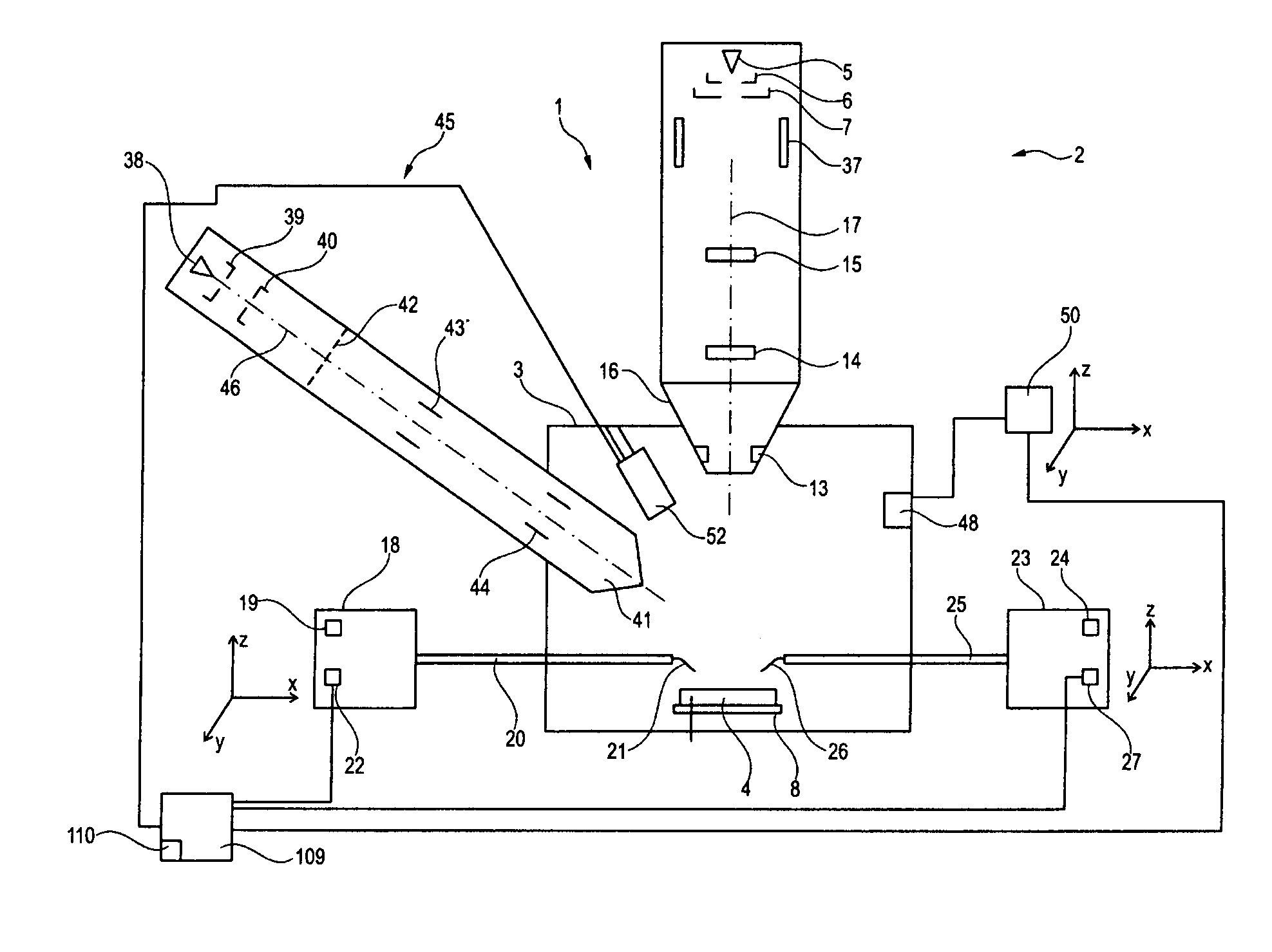
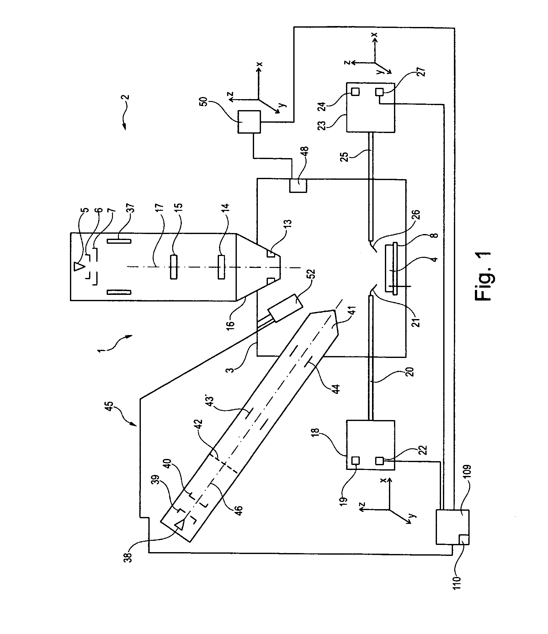
[0055]FIG. 1 shows a schematic representation of a particle beam device 1, with which the method according to the system described herein can be carried out. The particle beam device 1 has two particle beam columns, to be specific a first particle beam column 2 and a second particle beam column 45, which is arranged on a specimen chamber 3. The first particle beam column is formed as an electron beam column and is arranged vertically with regard to the specimen chamber 3.

[0056]The first particle beam column 2 has a beam generator 5 in the form of an electron source—a cathode—and a system consisting of a first electrode 6 and a second electrode 7. The second electrode 7 forms one end of a beam guiding tube (not represented). For example, the beam generator 5 is formed as a thermal field emitter. Electrons that emerge from the beam generator 5 are accelerated to a predeterminable potential on account of a potential difference between the beam generator 5 and the second electrode 7 and...


PUM


Abstract

The system described herein determines a distance of a component of a particle beam device from an object to the particle beam device and sets a position of the component in the particle beam device. The component is moved from a first starting position of the component relatively in the direction of an object, which is located in a second starting position, until the component makes contact with the object. When the component makes contact with the object, an adjusting path covered by the component and / or the object during the movement is determined. The adjusting path runs along a straight line that joins a first point on the component in the first starting position to a second point on the object in the second starting position that is arranged closest to the first point on the component along this line. The adjusting path corresponds to the distance.

Description

TECHNICAL FIELD[0001]The system described herein relates to a method for setting a position of at least one component of a particle beam device and to a particle beam device with which this method can be carried out. Furthermore, the system described herein relates to a method for measuring a distance of the component from the object.BACKGROUND[0002]Electron beam devices, in particular a scanning electron microscope (hereinafter also referred to as an SEM) and / or a transmission electron microscope (hereinafter also referred to as a TEM), are used for examining objects (specimens), in order to gain insights into the properties and behavior under certain conditions.[0003]In the case of an SEM, an electron beam (hereinafter also referred to as a primary electron beam) is generated by means of a beam generator and focused by a beam guiding system onto an object to be examined. By means of a deflecting device, the primary electron beam is guided in the form of a raster over a surface of ...

Claims


Application Information

Patent Timeline
Patent Type & Authority Applications(United States)
IPC IPC(8): H01J37/02H01J37/28
CPCH01J37/023H01J37/28H01J2237/2801H01J2237/10H01J2237/2007H01J2237/006
Inventor DOEMER, HOLGERSCHMAUNZ, ANDREAS
Owner CARL ZEISS MICROSCOPY GMBH
Learn More