

Blind area multi-picture video group display system for commercial vehicle
A group display, multi-screen technology, applied in vehicle parts, optical observation devices, transportation and packaging, etc., can solve the problems of less comprehensive information of auxiliary video images in blind spots, single display of alarm information and lights, and mutual influence of functions.
- Summary
- Abstract
- Description
- Claims
- Application Information
AI Technical Summary
Problems solved by technology
Method used
Image

Examples
Embodiment Construction
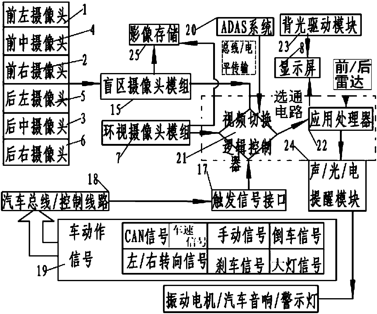
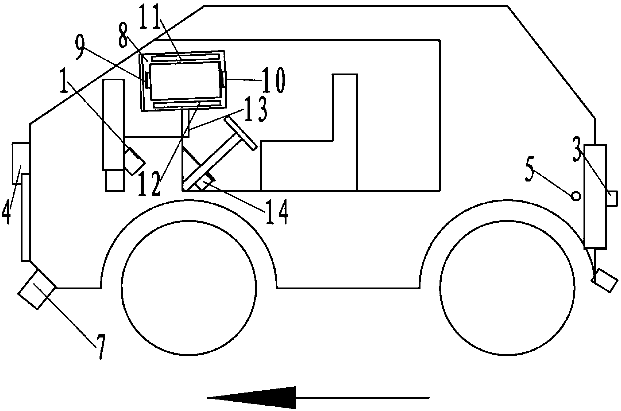
[0005] refer to Figure 1-17 shown, where in Figure 1-7 Among them, the commercial vehicle blind spot multi-screen video group display system of this embodiment includes an input unit, an application processor 22 electrically connected to the input unit, and an output unit electrically connected to the application processor 22;
[0006] The input unit comprises the video switching logic controller 21 that is used for the blind spot camera module 15 of taking pictures around the car, and the input terminal is electrically connected with the blind spot camera module 15 output; through the circuit.
[0007] The blind spot camera module 15 includes a front n-type camera system and / or a rear U-type camera system;
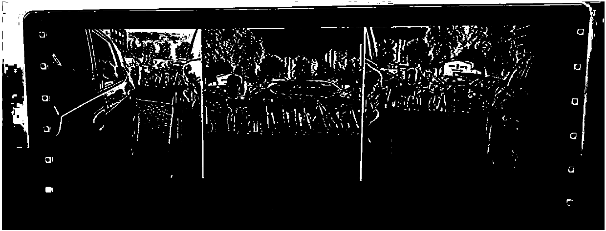
[0008] The output unit includes a display screen 8 for split-screen display or single-screen display of information captured by the blind spot camera module 15 , and the display screen 8 is electrically connected to the application processor 22 .
[0009] The present...
PUM
 Abstract
Description
Claims
Application Information