
Method for setting a position of a component of a particle beam device and particle beam device for carrying out the method

Pending Publication Date: 2020-05-07
CARL ZEISS MICROSCOPY GMBH
View PDF0 Cites 0 Cited by
  • Summary
  • Abstract
  • Description
  • Claims
  • Application Information

AI Technical Summary

Benefits of technology

This patent describes a system and method for positioning a component in a particle beam apparatus at a suitable distance from an object. By doing so, the component can perform its functions without interfering with other processes. For example, when the component is a gas feed device, it can supply enough gas to the object while ensuring that the particle beam is not blocked. Similarly, when the component is a particle detector, it can detect particles effectively without affecting the beam's trajectory. The system allows for automated positioning of the component and ensures rapid movement from a parked position to a processing position. The technical effects of this system include improved efficiency, precision, and control during particle beam processing.

Problems solved by technology

Therefore, the problem addressed by the system described herein is that of specifying a method and a particle beam apparatus with which a component of a particle beam apparatus, in particular a gas feed device, is positionable at a specific position as accurately as possible and very rapidly, without influencing the particle beam of the particle beam apparatus.

Method used


Image

  • Method for setting a position of a component of a particle beam device and particle beam device for carrying out the method
  • Method for setting a position of a component of a particle beam device and particle beam device for carrying out the method
  • Method for setting a position of a component of a particle beam device and particle beam device for carrying out the method

Examples


Embodiment Construction

[0066]Illustrative embodiments of the system described herein will now be described in relation to the drawings. It should be appreciated that the system described herein is not limited to the following illustrative embodiments, as other embodiments, for example, variations of the following illustrative embodiments, are possible, and intended to fall within the scope of the invention.

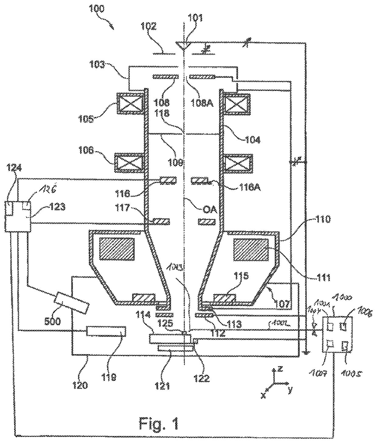
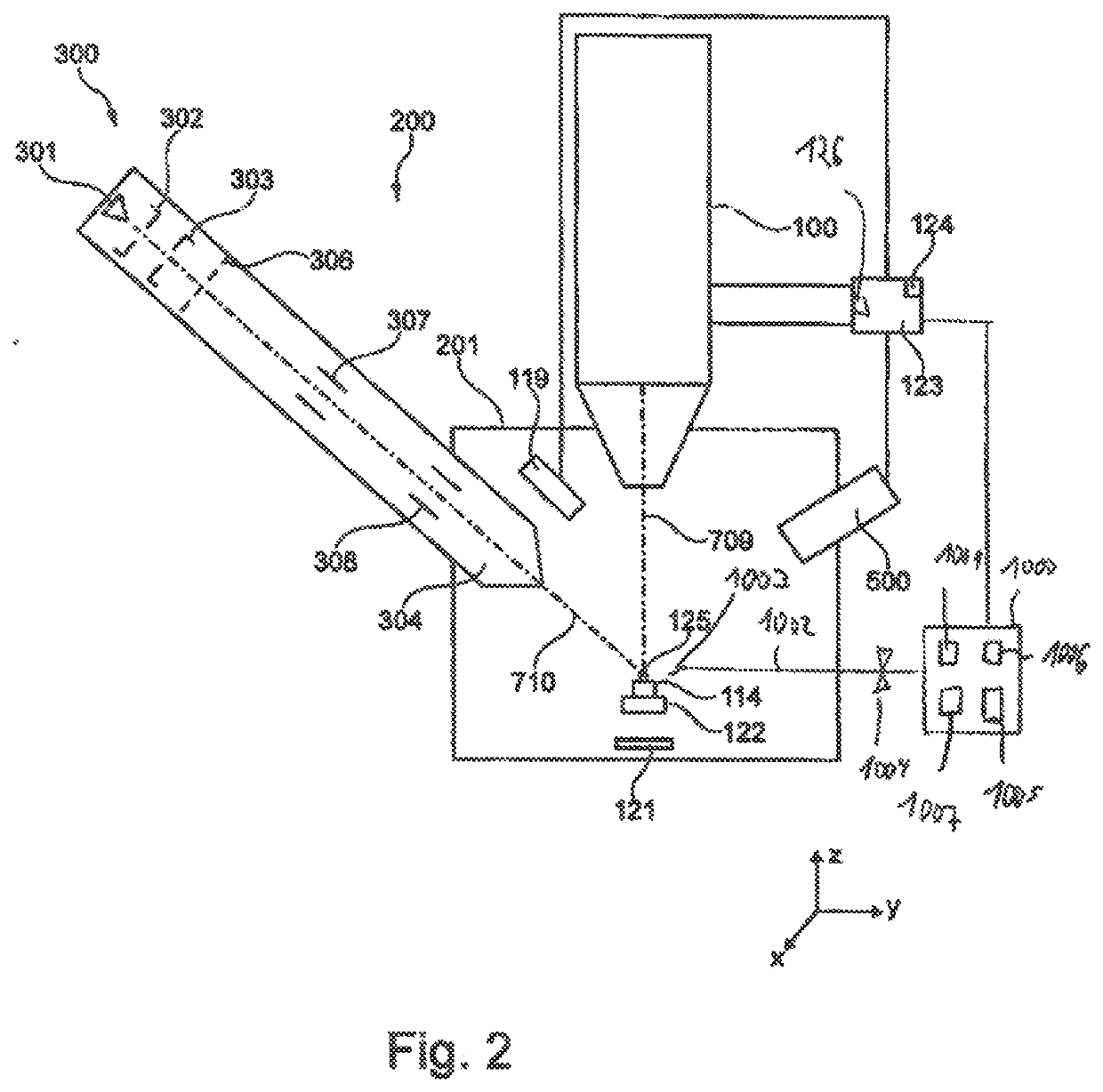
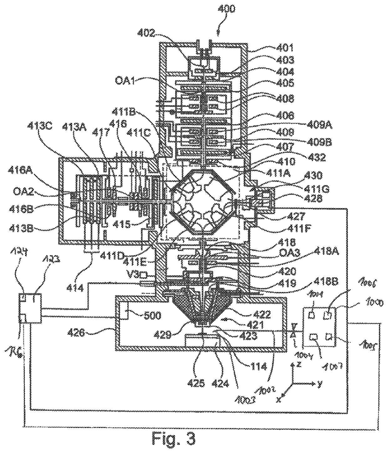
[0067]The system described herein is now explained in more detail by means of particle beam apparatuses in the form of an SEM and in the form of a combination apparatus, which has an electron beam column and an ion beam column. Reference is explicitly made to the fact that the system described herein may be used in any particle beam apparatus, in particular in any electron beam apparatus and / or in any ion beam apparatus. Furthermore, the system described herein is described with respect to a gas feed device. It is expressly pointed out that any component of a particle beam apparatus may be suitable for ...


PUM


Abstract

The invention relates to a method for setting a position of a component (1003) in a particle beam apparatus, and to a particle beam apparatus for carrying out the method, wherein the component (1003) is embodied as a gas feed device, as a particle detector and / or as a beam detector, and wherein the method comprises the following steps: aligning the component (1003) with a coincidence point (2000) of a particle beam of the particle beam apparatus, determining a rotation angle (a) of a rotation of an object carrier about a rotation axis (603), loading a position of the component (1003) associated with the rotation angle (a) from a database into a control unit, transmitting a control signal from the control unit to a drive unit for moving the component (1003), and moving the component (1003) into the position loaded from the database by means of the drive unit, wherein the component (1003) arranged in the loaded position is at a predefinable distance (OAB) from the object.

Description

CROSS-REFERENCE TO RELATED APPLICATION[0001]This application claims the benefit of German patent application no. 10 2018 216 968.3, filed on Oct. 2, 2018, which application is incorporated herein by reference.TECHNICAL FIELD[0002]The system described herein relates to particle beam analysis, more particularly to a method for setting a position of at least one component of a particle beam apparatus, and to a particle beam apparatus with which this method is able to be carried out.BACKGROUND OF THE INVENTION[0003]Electron beam apparatuses, in particular a scanning electron microscope (also referred to as SEM below) and / or a transmission electron microscope (also referred to as TEM below), are used to examine objects (samples) in order to obtain knowledge in respect of the properties and behavior under certain conditions.[0004]In an SEM, an electron beam (also referred to as primary electron beam below) is generated by means of a beam generator and focused onto an object to be examined...

Claims


Application Information

Patent Timeline
IPC IPC(8): H01J37/28H01J37/26H01J37/10
CPCH01J2237/20214H01J37/28H01J37/10H01J2237/24585H01J37/265H01J37/244H01J37/3244H01J2237/202H01J2237/245H01J37/26H01J37/023
Inventor SCHMAUNZ, ANDREASWALTER, GEROSTENKE, BERND
Owner CARL ZEISS MICROSCOPY GMBH
Learn More