Electroacoustic converter and electronic device

a technology of electroacoustic converter and electronic device, which is applied in the direction of electrical transducers, earpiece/earphone attachments, transducer details, etc., can solve the problems of difficult flexibly dealing with peak level adjustment in a specific frequency band, and sound waves cannot be generated with desired frequency characteristics, etc., to achieve the effect of reducing pitch

Active Publication Date: 2016-04-28
TAIYO YUDEN KK
View PDF2 Cites 10 Cited by
  • Summary
  • Abstract
  • Description
  • Claims
  • Application Information

AI Technical Summary

Benefits of technology

[0010]In light of the aforementioned situations, an object of the present invention is to provide an electroacoustic converter capable of obtaining desired frequency characteristics easily, as well as an electronic device equipped with such converter.
[0016]With the electroacoustic converter, sound waves generated by the electromagnetic sounding body are formed by composite waves having a sound wave component that propagates to the second space by vibrating the first vibration plate of the piezoelectric sounding body, and a sound wave component that propagates to the second space via the passage. Accordingly, sound waves output from the piezoelectric sounding body can be adjusted to desired frequency characteristics by optimizing the size of the passage, number of passages, etc. The electromagnetic sounding body is typically constituted so that it generates sound waves that are lower in pitch than sound waves generated by the piezoelectric sounding body. This way, frequency characteristics having a sound pressure peak in a desired low-pitch band can be obtained with ease, for example.
[0017]Also, because the passage is provided at the piezoelectric sounding body, the resonance frequencies of the first vibration plate (frequency characteristics of the piezoelectric sounding body) can be adjusted by the mode of the passage. This makes it easy to achieve desired frequency characteristics, such as flat composite frequencies around the cross point between the low-pitch sound characteristic curve by the electromagnetic sounding body and the high-pitch sound characteristic curve by the piezoelectric sounding body.
[0018]In addition, the passage functions as a low-pass filter that cuts, from among the sound waves generated by the electromagnetic sounding body, those high-frequency components of or above a specified level. This way, sound waves in a specified low-frequency band can be output without affecting the frequency characteristics of high-pitch sound waves generated by the piezoelectric sounding body.

Problems solved by technology

However, the constitution of Patent Literature 2 presents a problem in that, because the dynamic driver is blocked off by the front cover, sound waves cannot be generated with desired frequency characteristics.
To be specific, it is difficult to flexibly cope with the peak level adjustment in a specific frequency band, or the optimization of frequency characteristics at the cross point between the low-pitch sound characteristic curve and high-pitch sound characteristic curve, among others.

Method used


Image

  • Electroacoustic converter and electronic device
  • Electroacoustic converter and electronic device
  • Electroacoustic converter and electronic device

Examples


first embodiment

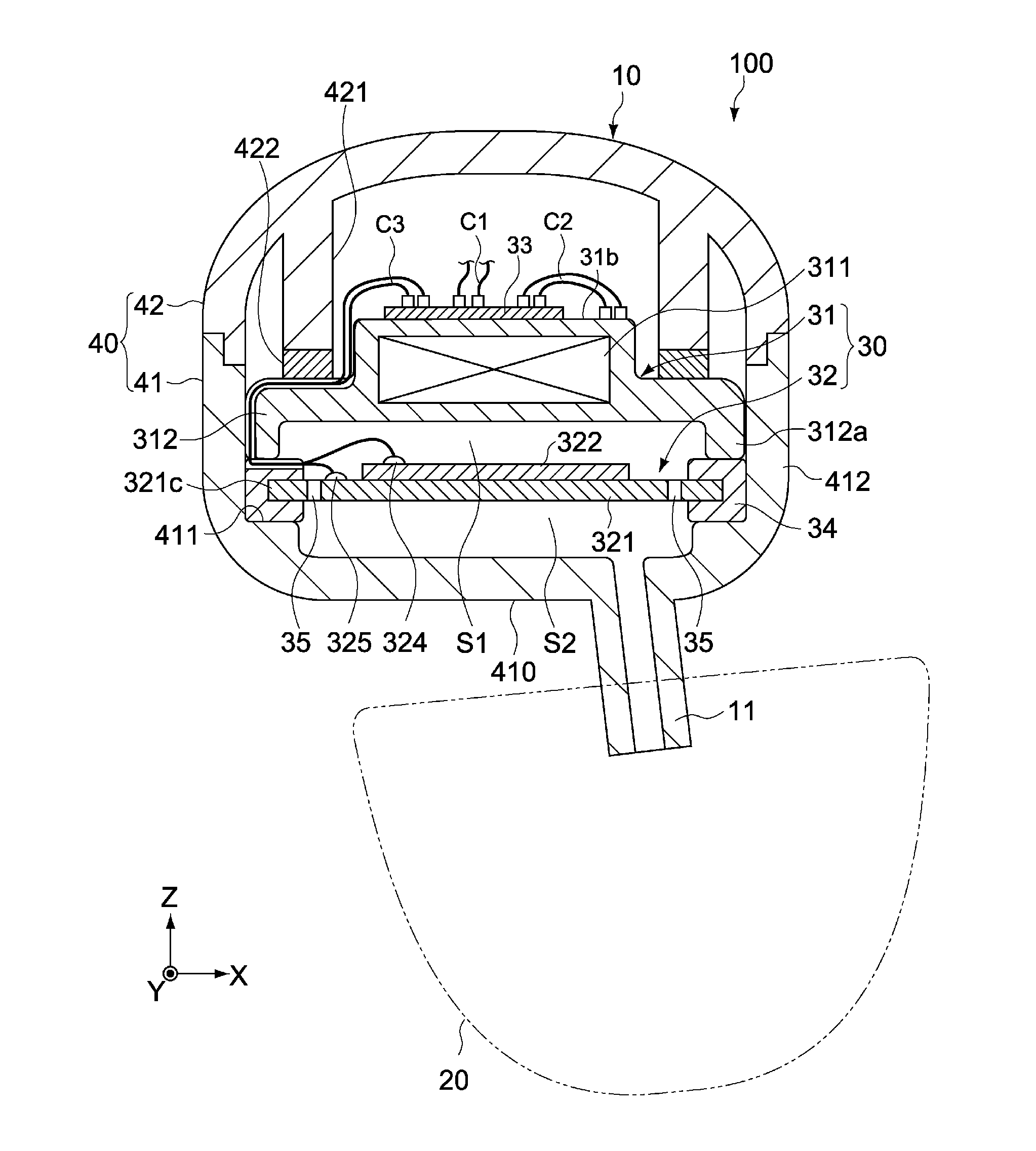
[0061]FIG. 1 is a schematic lateral section view showing the constitution of an earphone 100 as an electroacoustic converter pertaining to an embodiment of the present invention.

[0062]In the figure, the X-axis, Y-axis, and Z-axis represent three axial directions crossing one another at right angles.

Overall Constitution of Earphone

[0063]The earphone 100 has an earphone body 10 and earpiece 20. The earpiece 20 is attached to a sound path 11 of the earphone body 10, while constituted in such a way that it can be worn on the user's ear.

[0064]The earphone body 10 has a sounding unit 30, and a housing 40 that houses the sounding unit 30.

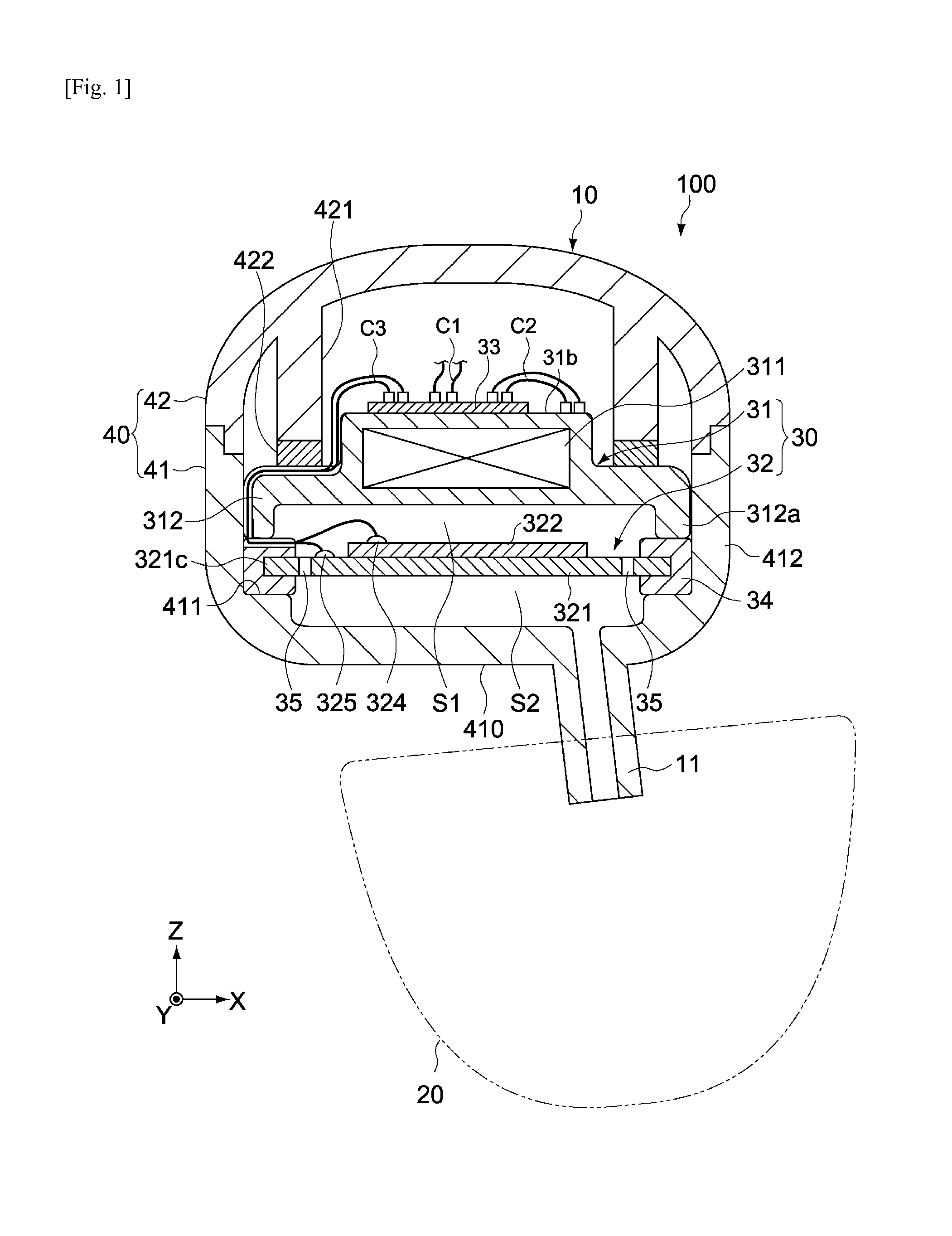
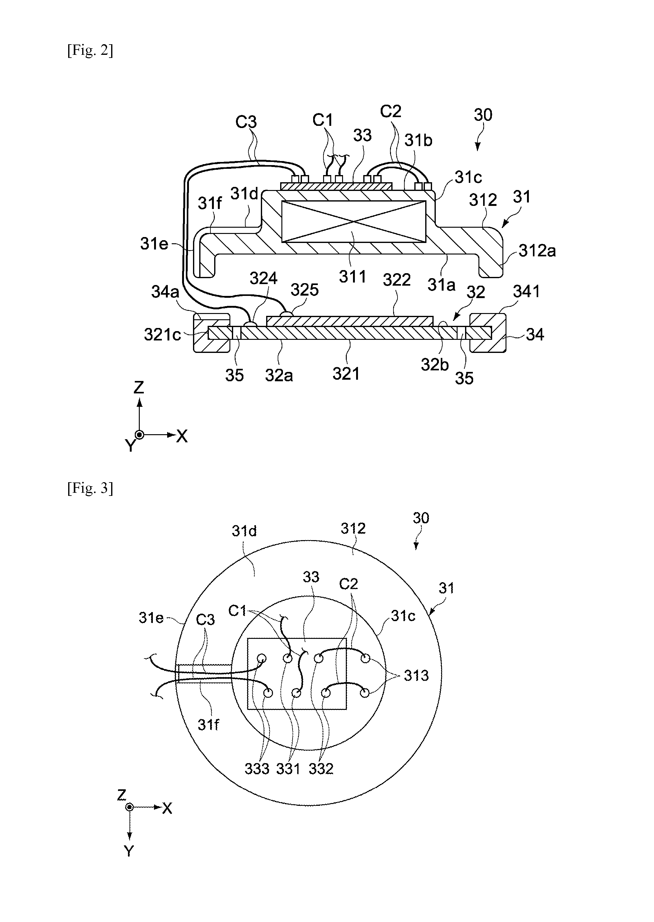
[0065]The sounding unit 30 has an electromagnetic sounding body 31 and piezoelectric sounding body 32. The housing 40 has an enclosure 41 and cover 42.

Enclosure

[0066]The enclosure 41 has the shape of a cylinder with a bottom and is typically constituted by injection-molded plastics. The enclosure 41 has an interior space in which the sounding unit 30 is ho...

second embodiment

[0117]FIG. 12 is a schematic section view of an earphone 200 pertaining to another embodiment of the present invention. Constitutions different from those of the first embodiment are primarily explained below, and the same constitutions as in the aforementioned embodiment are not explained or explained briefly using the same symbols.

[0118]The earphone 200 of this embodiment is different from the aforementioned first embodiment in terms of the constitution of a sounding unit 50, especially that of a piezoelectric sounding body 52. The piezoelectric sounding body 52 has a vibration plate 521, and the piezoelectric element 322 joined to one principle surface (principle surface facing the first space S1 in this example) of the vibration plate 521.

[0119]FIG. 13 is a schematic plan view showing the constitution of the piezoelectric sounding body 52. As shown in FIG. 13, multiple (three in the illustrated example) projecting pieces 521g that project radially outward in the diameter directi...


PUM


Abstract

In an embodiment, an electroacoustic converter (earphone 100) has an enclosure 41, piezoelectric sounding body 32, electromagnetic sounding body 31, and passage 35. The piezoelectric sounding body 32 includes a first vibration plate 321 having a periphery supported directly or indirectly on the enclosure 41, and a piezoelectric element 322 placed at least on one side of the vibration plate 321. The piezoelectric sounding body 32 has a second vibration plate and divides the interior of the enclosure 41 into a first space S1 and a second space S2. The electromagnetic sounding body 31 is placed in the first space S1. The passage 35 is provided in or around the piezoelectric sounding body 32 to connect the first space S1 and second space S2. The electroacoustic converter is capable of obtaining desired frequency characteristics easily.

Description

BACKGROUND[0001]1. Field of the Invention[0002]The present invention relates to an electroacoustic converter that can be applied to earphones, headphones, mobile information terminals, etc., for example, and an electronic device equipped with such converter.[0003]2. Description of the Related Art[0004]Piezoelectric sounding elements are widely used as simple means for electroacoustic conversion, where popular applications include earphones, headphones, and other acoustic devices as well as speakers for mobile information terminals, etc. Piezoelectric sounding elements are typically constituted by a vibration plate and a piezoelectric element attached on one side or two sides of the plate (refer to Patent Literature 1, for example).[0005]On the other hand, Patent Literature 2 describes headphones equipped with a dynamic driver and a piezoelectric driver, where these two drivers are driven in parallel to allow for wide playback bandwidths. The piezoelectric driver is provided at the c...

Claims


Application Information

Patent Timeline
Patent Type & Authority Applications(United States)
IPC IPC(8): H04R17/00
CPCH04R17/00H04R1/265H04R2499/11H10N30/50H04R1/1075H04R1/2811
Inventor DOSHIDA, YUTAKAMATSUI, YUKIHIROHAMADA, HIROSHI
Owner TAIYO YUDEN KK
Why Eureka
Try Eureka