Vibratory conveyor with non-biased oscillation

a conveyor and non-biased technology, applied in conveyors, conveyors, jigging conveyors, etc., can solve the problems of limiting the usefulness of tough durable workpiece handling, affecting the reliability of the floor space requirements, and the vibratory motors of these conveyors are unable to provide only back and forth motion or vibration, so as to achieve simple rheostat control, reduce the effect of floor space requirements and easy adjustment in force and frequency

Inactive Publication Date: 2008-07-15
ROBOSHOP
View PDF17 Cites 7 Cited by
  • Summary
  • Abstract
  • Description
  • Claims
  • Application Information

AI Technical Summary

Benefits of technology

[0009]It is another object for a vibratory drive to provide quiet, efficient operation with vibrations that are confined to the plane of the trough, without significant components in the vertical direction, i.e., perpendicular to the trough.
[0011]The specific material is not critical, except that it must favor moving the articles in a given direction. Some convenient directional fabrics can have a brush-like surface, i.e., surface fibers or hairs that bend or lean in one direction, or may even have a more-or-less scaly surface, like snake skin or fish skin. The vibratory motor keeps the motion in the back and forth direction, with almost no vertical component, instead of the conventional jerky upward motion that is typical of conventional vibratory conveyor drives. This makes for quieter operation and is less likely to produce shaking that can damage delicate workpieces.
[0016]The vibratory drive motor for this is designed to produce planar motion, i.e., without the vertical component that is produced by conventional vibratory drives. Consequently, the vibratory drive employed in this invention is quieter, and can be easily adjusted in force and frequency by simple rheostat controls.
[0017]The conveyors of this invention can replace conventional belt-type conveyors while providing advantages in versatility, reliability reduction in floor space requirements, gentler part handling, and costs. The linear flow motion technology offers unmatched part handling capabilities, with a rugged, low profile, and quiet part handling system.
[0018]The part motion direction or feed direction can be changed quickly and easily, simply by changing the direction of the biased material. The strips of biased material may be secured with Velcro® or a similar hook-and-loop system. The low profile of the conveyors provides tight product transfers and the ability to fit into space-constrained areas. The brush-like material provides additional benefits in the handling of polished or fragile parts, but can easily handle standard parts also. These vibratory conveyors can be made in a multitude of widths and lengths, and can be easily interconnected for longer length requirements.
[0019]The linear flow motion employed in this invention eliminates the vertical motion component that is inherent in standard vibratory conveying systems. The conveying surface is reciprocated in a flat, linear motion, reducing noise and removing unwanted vibration transfer both to the conveyed part and to any connected equipment. The bias direction of the brush or similar material controls the direction of part movement. The technology offers the unique capability of a full 180° direction reversal, without additional components such as belts, shafts, or pulleys. Because there is no belt involved, reversal of parts direction is simple to accomplish. The operator can simply peel back the brush-like material from the hook-and-loop backing and pull it off, and then lay it in the opposite direction. Maintenance is also simple. The brush-like material can be cleaned by vacuuming, or it may be removed and washed. The vibratory strips are favorably formed of a polyethylene material with a rubber backing, which is water and solvent resistant.

Problems solved by technology

These systems are loud and somewhat inefficient, and produce shaking which limits their usefulness to handling of tough durable workpieces.
Previously, vibratory motors for these conveyors have been unable to provide motion only in a back and forth direction, or to provide the vibrations without the rough shaking and jerking that can damage the more delicate parts and components on the assembly line.

Method used


Image

  • Vibratory conveyor with non-biased oscillation
  • Vibratory conveyor with non-biased oscillation
  • Vibratory conveyor with non-biased oscillation

Examples


Embodiment Construction

)

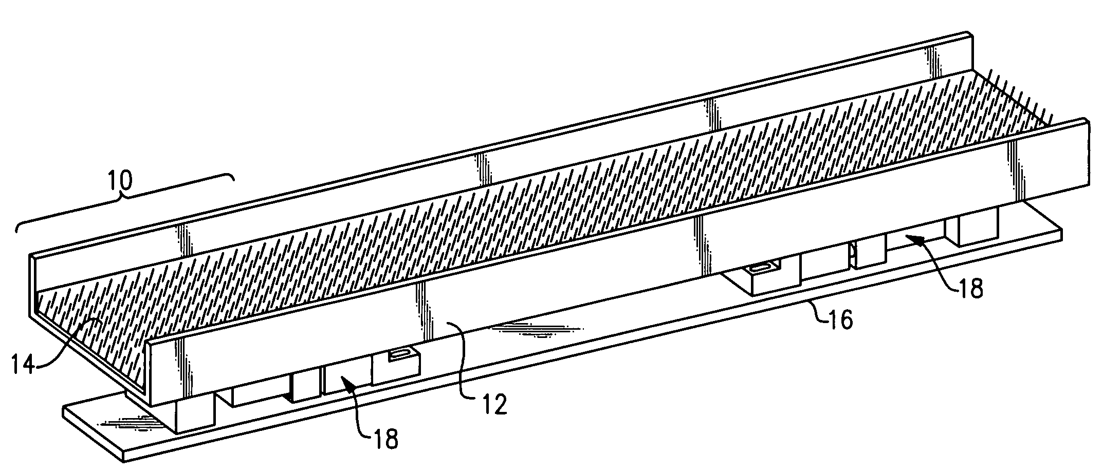
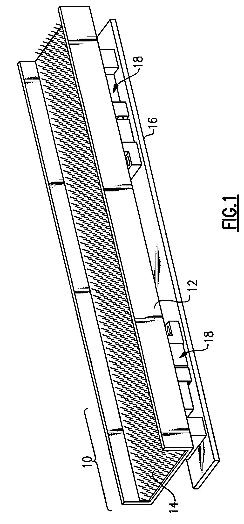
[0029]With reference to the Drawing, and initially to FIG. 1, a linear vibratory conveyor 10 has a trough 12 containing a brushlike linear fabric material 14 which is conveying material that the parts are placed upon. A base plate 16 beneath the trough 12 is affixed onto a table, floor or other support, and a linear vibratory drive motor, or in this embodiment, a pair of drive motors 18, is mounted on the base plate 16, with the tray or trough 12 being supported on the drive motors 18.

[0030]The trough 12 oscillates longitudinally, that is, back and forth in its own plane, so that there is no significant component of vertical motion of the trough. Here the term “vertical” means in the direction normal to the plane of the trough, which can be inclined somewhat. The oscillation is uniform, and can be sinusoidal or harmonic, so that the only factor influencing the conveyance is the bias of the surface material 14. The conveying material 14 is biased so that it is smooth in one directio...


PUM


Abstract

A vibratory conveyor has a bed or trough that carries the workpieces, and supported above a base plate. A vibratory motor employs linear bearing to provide vibratory that is kept in the plane of the conveyor bed. A directional fabric material lying on the trough is smooth or slippery in one direction but grips the workpieces in the opposite direction. The vibratory motor keeps the motion in the back and forth direction, with almost no vertical component, for quieter operation and without shaking that can damage delicate workpieces. The direction of motion can be selected by orienting the fabric.

Description

[0001]Applicant claims priority under 35 U.S.C. 119(e) of Provisional Appln. 60 / 702,102, filed Jul. 22, 2005.BACKGROUND OF THE INVENTION[0002]This invention concerns vibratory conveyors, which may be used for conveying articles or parts from one location to another, or as a parts feeder for bringing articles or parts to a given process step, or as an orientation device for orienting parts so that a process step may be carried out more efficiently.[0003]The invention is more concerned with devices which use vibration to convey and / or orient parts on a reciprocating trough or platform.[0004]In vibratory conveyors, there is a bed or trough that carries the workpieces, a vibratory motor that provides vibratory motion. Conventional unidirectional vibratory drive motors produce a jumpy or jerky motion with a significant vertical component. These miss out on the advantages possible with a more-or-less harmonic vibratory motion, where motion is confined to the horizontal plane, i.e., the pl...

Claims


Application Information

Patent Timeline
Patent Type & Authority Patents(United States)
IPC IPC(8): B65G27/00B65G27/34
CPCB65G27/24B65G27/04
Inventor GIOVINAZZO, FRANK
Owner ROBOSHOP
Why Eureka
Try Eureka