Hot compressed gas vehicle

a technology of compressed gas and hot air, which is applied in the direction of light-to-electric conversion, electric devices, transportation and packaging, etc., can solve the problems of low efficiency, no alternative system has come into widespread use, and low energy efficiency of internal combustion engine vehicles, so as to achieve less pollution, less complex, and more energy-efficient

Inactive Publication Date: 2009-11-26
ADLI MANOUCHER
View PDF20 Cites 13 Cited by
  • Summary
  • Abstract
  • Description
  • Claims
  • Application Information

AI Technical Summary

Benefits of technology

[0011]Thus, there is a continuing need for improved vehicle drive systems that are more energy efficient, produce less pollution, transfer power to the motive means in a less complex, lighter weight and more effective manner and recover and use energy dissipated during breaking and coasting.
[0015]An object of the present invention is to provide a compressed hot air / steam powered vehicle that is light weight and energy efficient.

Problems solved by technology

Because of the high state of development of the internal combustion engine and certain problems with these alternative systems such as low efficiency, short range and other problems, none of these alternative systems have come into widespread use.
Internal combustion engine vehicles have low energy efficiency.
They require oil to reduce friction and their weight requires heavy structures for support.
Therefore, most of the energy of the hot pressurized gas of combustion is wasted in the form of friction and heat escaping into the atmosphere, making the combustion engine vehicles very inefficient.
Thus, both the combustion and the way the combustion energy is transferred to the wheel are inefficient.
Also, internal combustion engines are not fully efficient, wasting considerable amounts of energy in the form of heat that must be passed to the atmosphere though a radiator and exhaust system.
During driving under conditions in which the main engine is inefficient, such as stop-and-go urban driving, the compressed air powers the same drive train with the main engine turned off.
While improving efficiency under limited conditions, this system still has most of the disadvantages of the internal combustion engine and is very heavy, requiring both internal combustion and air drive system, reducing efficiency.
Another hybrid system requiring an electric motor and flywheel drive for an air compressor is described by Yeh in U.S. Pat. No. 4,163,367, and has similar problems with weight and complexity.
Again, as merely a supplement to a main engine, the weight, complexity and cost of the auxiliary system are not generally justified by any efficiency increases.
Since no source of energy is furnished to replenish energy lost to friction in the system, the tank will quickly run out of air.
Even if the tank were filled before beginning a drive, the vehicle would have an extremely short range.

Method used


Image

  • Hot compressed gas vehicle
  • Hot compressed gas vehicle
  • Hot compressed gas vehicle

Examples


Embodiment Construction

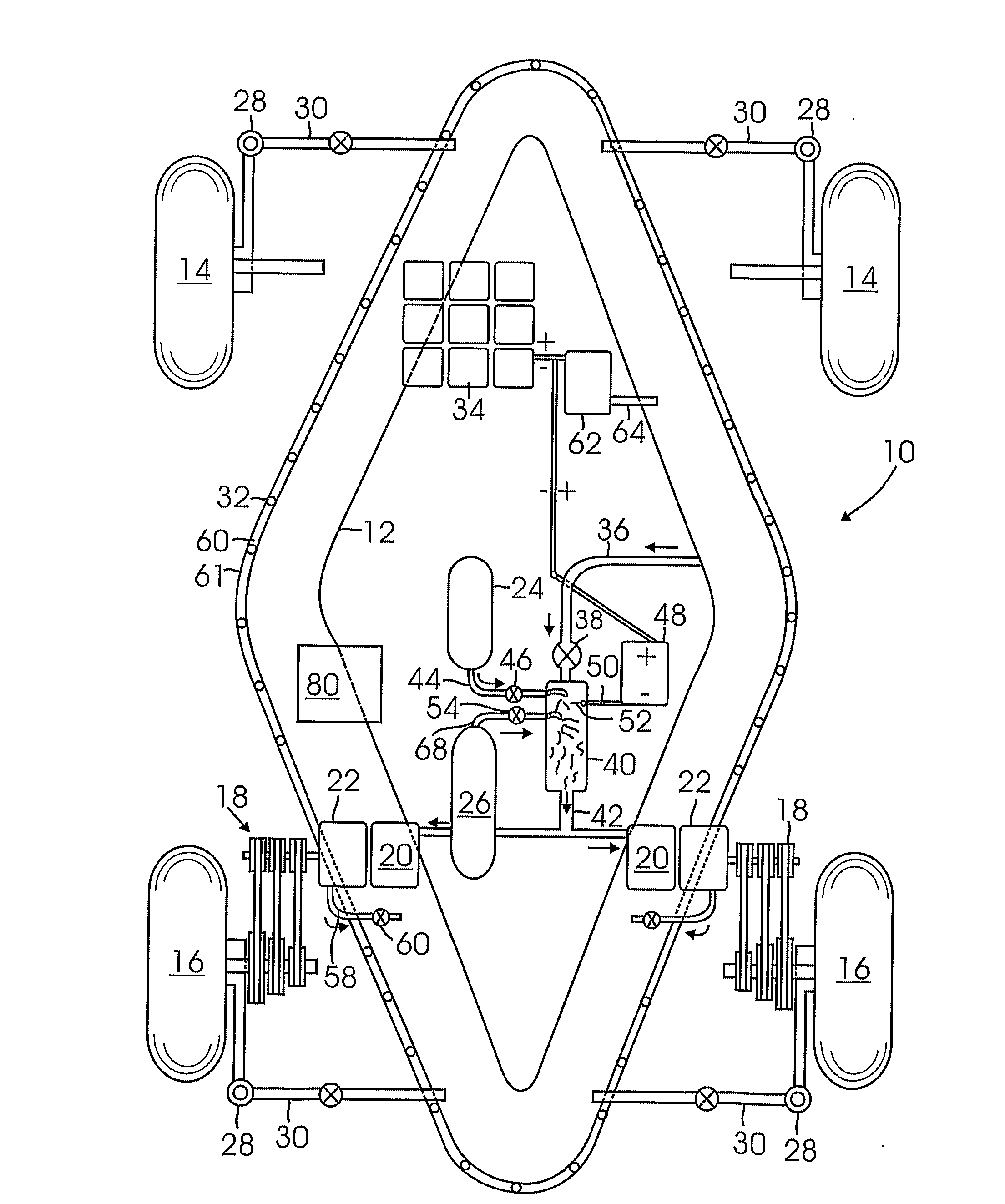
[0028]FIG. 1 schematically illustrates a road vehicle 10 such as a passenger automobile or the like using an air powered drive system according to an embodiment of the present invention. An air tank 12 is provided for storing compressed air. In the illustrated example, the tank 12 surrounds the perimeter of a base of the vehicle and has a diamond shape with pointed ends at the front and rear. While this position is preferred since it provides an energy absorbing structure in the event of a collision, the tank 12 may have any suitable shape and can be located in any suitable position. Typically, the tank 12 can accommodate 100 to 1000 or more psi pressure and can be formed from any suitable material, such as metals, fiber reinforced plastics such as carbon fibers in a resin matrix, etc.

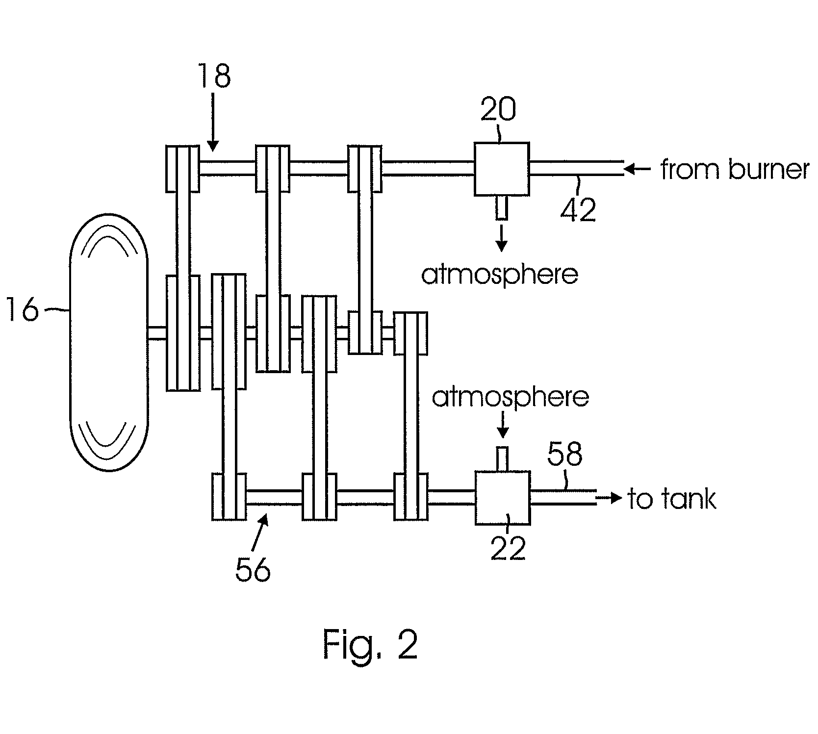
[0029]The vehicle 10 is supported on a plurality of conventional wheels. Here four wheels including two forward wheels 14 and two aft wheels 16 are shown. An air motor 20 through a variable speed trans...


PUM


Abstract

A compressed-air powered drive system for a vehicle (10) or a propeller-driven aircraft (12). In a land vehicle (10), the drive system includes a plurality of air motors (20) each driving a wheel (16) through a transmission device (18). Compressed air from an air storage tank (12) is supplied through a heat exchanger (40) to drive air motors. A fuel is burned in the heat exchanger (40) to provide hot, high pressure air to the first air motors. Water may be injected into the heat exchanger to provide a hot steam. A plurality of air pumps (22) are engaged with and driven by the wheels to pump air into the tank during driving. When braking, the air pumps (22) driven by the wheels (16) recapture kinetic energy by pumping air into the tank. The air motors can also act as pumps to pump air into the tank during braking by reversing the transmission devices.

Description

BACKGROUND OF THE INVENTION[0001]1. Field of the Invention[0002]This invention relates to apparatus for powering a vehicle capable of carrying people, cargo, etc. in which the motive energy is derived from compressed air.[0003]2. Description of the Related Art[0004]While most land vehicles, such as automobiles, trucks, etc. and many light aircrafts are powered by internal combustion engines, a number of other drive systems have been proposed. These include gas turbine engines, steam engines, electric battery power, etc. and combinations of these systems. Because of the high state of development of the internal combustion engine and certain problems with these alternative systems such as low efficiency, short range and other problems, none of these alternative systems have come into widespread use. Internal combustion engine vehicles have low energy efficiency. The main reason for this is that in the internal combustion engine, energy produced in the form of hot pressurized gas at co...

Claims


Application Information

Patent Timeline
Patent Type & Authority Applications(United States)
IPC IPC(8): B60K3/00B64D33/00
CPCB60K3/00B60K6/12B60K7/0023B60K17/043B60K2007/0061B60L8/00Y02T10/648B60L2220/46B64D27/02Y02T10/6208Y02T10/646Y02T10/7083Y02T50/44B60L8/003Y02T10/62Y02T10/64Y02T10/7072Y02T50/40
Inventor ADLI, MANOUCHER
Owner ADLI MANOUCHER
Why Eureka
Try Eureka