Ultrasound diagnostic device
- Summary
- Abstract
- Description
- Claims
- Application Information
AI Technical Summary
Benefits of technology
Problems solved by technology
Method used
Image
Examples
first embodiment
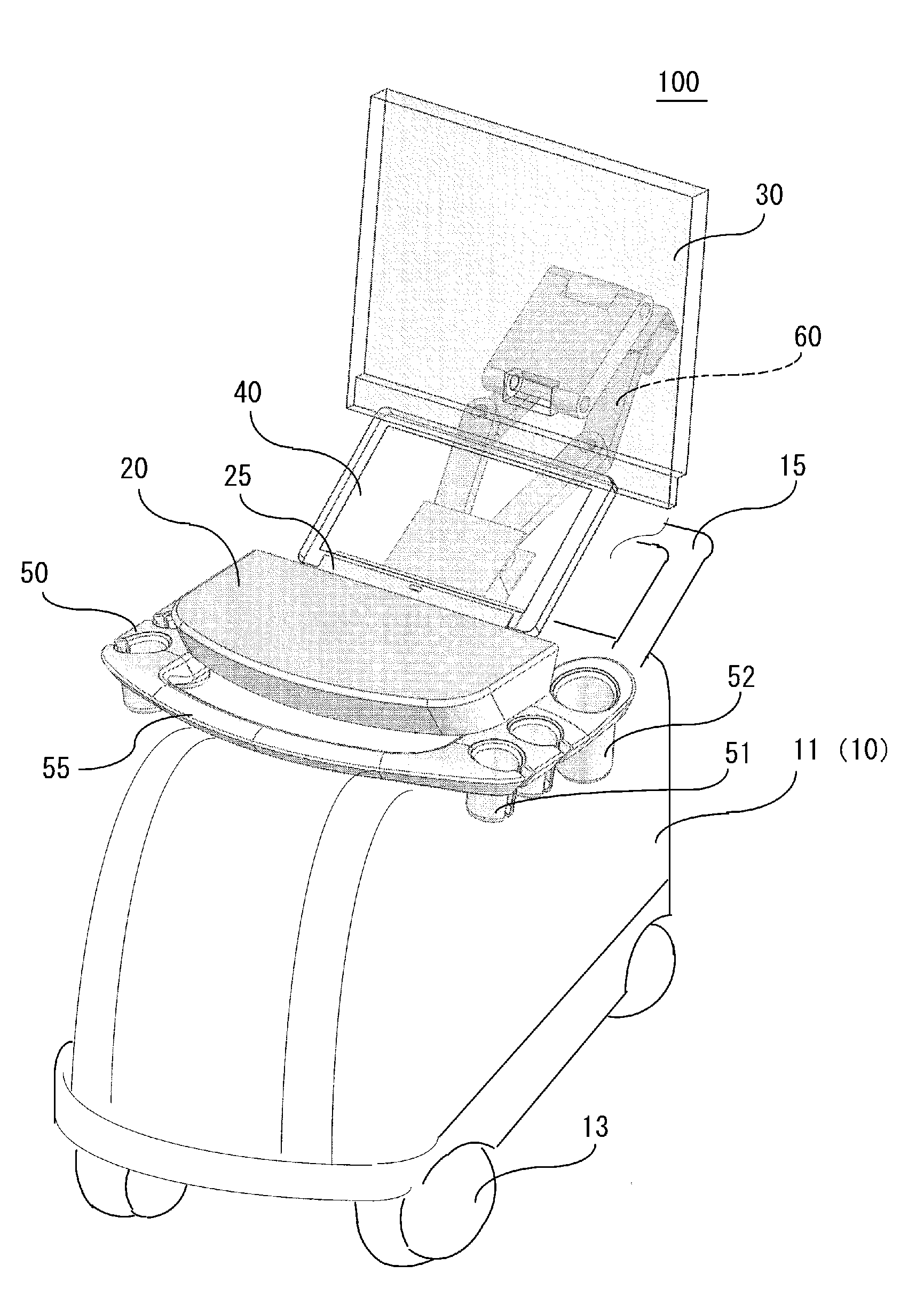
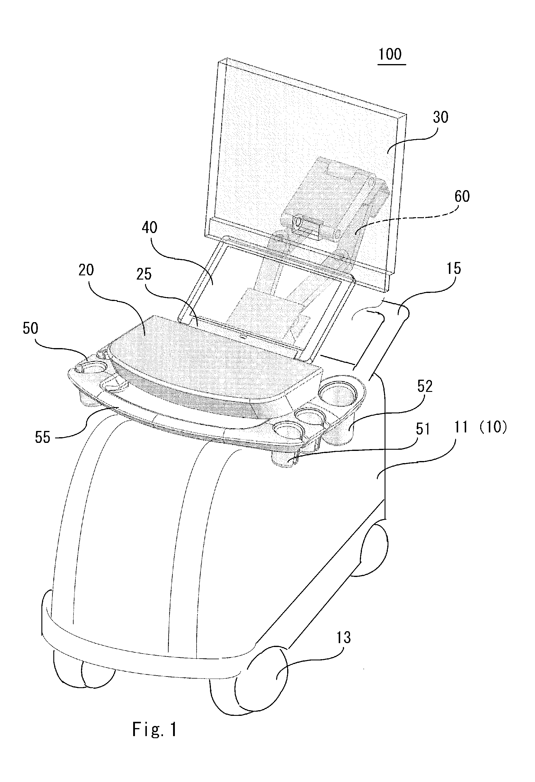
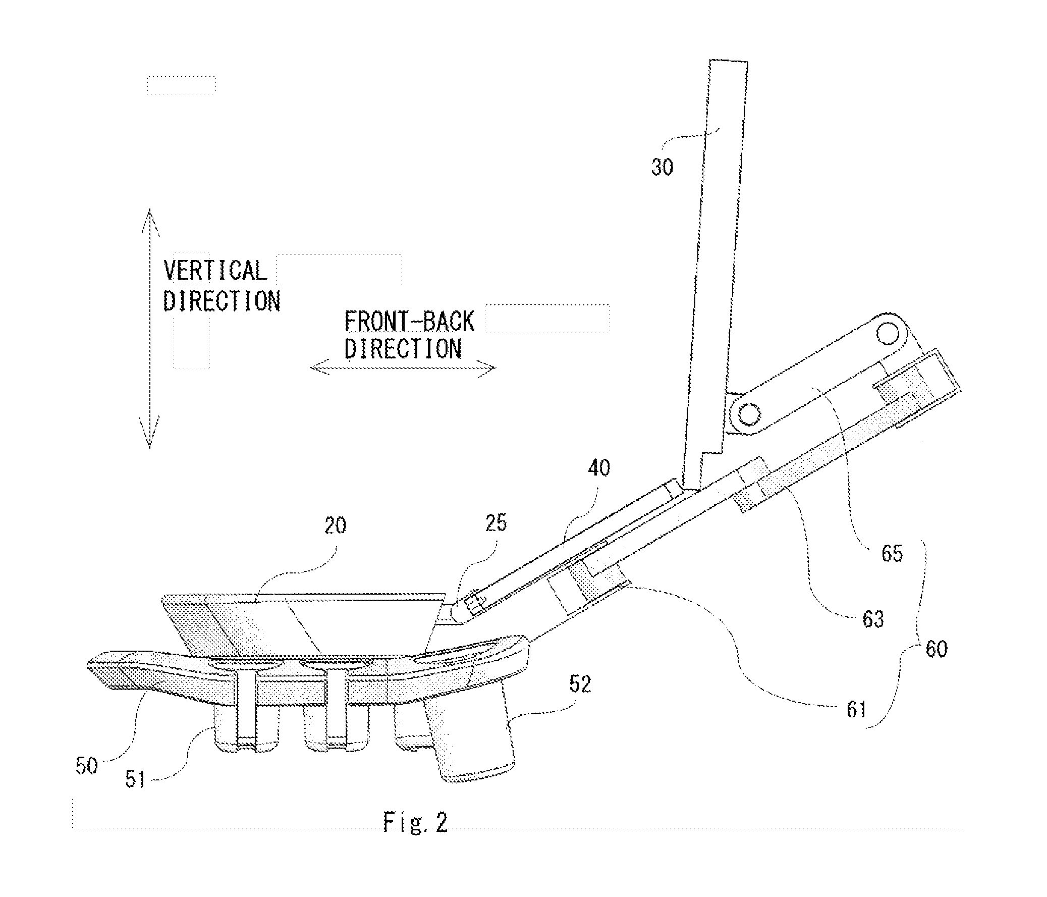
[0039]FIG. 1 is a perspective view illustrating an overall outline of an ultrasound diagnostic device 100 of a first embodiment, and FIG. 2 is a side view illustrating main parts of the ultrasound diagnostic device shown in FIG. 1. In the figures, a left side is a front side of the device, and a side opposite thereto is a rear side. As shown in the figures, the ultrasound diagnostic device 100 includes a main body 10, an operation panel 20 fixed to the main body 10 through a support mechanism, two displays 30 and 40, and a probe housing 50 for storing an ultrasound probe (not shown), as main components. The displays 30 and 40 have respectively independent functions and thus are not in a main-sub relationship, but hereinafter, for ease of description, the display (first display) 30 is referred to as a main display 30, the display (second display) 40 is referred to as a sub display 40. Further, when it is not necessary that the displays 30 and 40 are distinguished from each other, the...
second embodiment
[0073]An ultrasound diagnostic device of a second embodiment is characterized in that a turning function of a display panel supported by a main body is additionally provided.
[0074]That is, in the ultrasound diagnostic device of this embodiment, the supporter of the first display includes the rotating part fixed to the rear surface of the display panel, the expansion / contraction mechanism part that is fixed to the main body side at one end thereof and has the variable distance between the main body and the other end thereof, and the intermediate member that connects the rotating part to the expansion / contraction mechanism part. Here, the rotating part is fixed to the rear surface of the display surface through a pivot part fixed to the rear surface, and the display panel is supported to the rotating part in a turnable manner (Aspect 1.
[0075]Alternatively, the ultrasound diagnostic device of this embodiment has a characteristic that the supporter of the first display supported by the ...
modification example
[0088]Instead of the link part 63 of the second embodiment, a modification example of the supporter (connecting mechanism) 60 that employs a slide mechanism are shown in FIGS. 17 to 19. FIG. 17 is a perspective view illustrating the supporter 60 when seen on a rear side of the device, FIG. 18 is a side view illustrating a state where the sub display 40 is connected to the display connection unit 25, and FIG. 19 is a side view illustrating a state where the sub display 40 is detached from the display connection unit 25. In the figures, the same reference numerals are given to the same components as in the first and second embodiments.
[0089]As shown in the figures, the supporter 60 of a display employed in an ultrasound diagnostic device of this modification example employs a slide mechanism 630 as a mechanism that moves the main display 30 in a front-back direction. The slide mechanism 630 includes a hollow cylindrical body 635 and a slider 636 that slides inside the cylindrical body...
PUM
 Abstract
Description
Claims
Application Information
 - R&D
- Intellectual Property
- Life Sciences
- Materials
- Tech Scout
- Unparalleled Data Quality
- Higher Quality Content
- 60% Fewer Hallucinations
Browse by: Latest US Patents, China's latest patents, Technical Efficacy Thesaurus, Application Domain, Technology Topic, Popular Technical Reports.
© 2025 PatSnap. All rights reserved.Legal|Privacy policy|Modern Slavery Act Transparency Statement|Sitemap|About US| Contact US: help@patsnap.com


