Trim retainer - stab clip

a retainer and clip technology, applied in the direction of snap fasteners, buckles, transportation and packaging, etc., can solve the problems of poor retention of retainer detents, clip not providing simultaneous means of “float” tolerance variation, and clip retention in the molded clip position (within the doghouse), so as to improve molding, eliminate tuning, and improve the effect of retention effor

Active Publication Date: 2016-05-12
MAGNA INTERNATIONAL INC
View PDF3 Cites 19 Cited by
  • Summary
  • Abstract
  • Description
  • Claims
  • Application Information

AI Technical Summary

Benefits of technology

[0006]The present invention is directed to a trim retainer assembly having a clip portion with a base and a molded housing (or “doghouse”), having at least one keyhole. The bore of the molded keyhole in the doghouse is smooth for improved molding and elimination of tuning since there are no detents in the bore to tune or maintain. The base is provided with a pair of flexible arms (or “stab arms”) with self detent features that pass through an opening in the doghouse to provide clip retention and, at the same time, “float”. The pair of flexible arms also have clip centering detents. The housing with the keyhole bore in combination with the clip portion with the pair of arms provides the superior combination of operable clip detent, retention effort, consistent insertion / extraction, float, centering and anti-rotation, and simplification of tooling. The clip platform is also adaptable to any different styles / setup heights of molded clips.

Problems solved by technology

Known clips typically have a built-in means of detent to provide retention, however, the clips do not provide a simultaneous means for “float” tolerance variation.
There is poor clip retention in the molded clip positions (within the doghouses) having retainer detents (clip keyholes).
This is particularly a problem with molded thermoplastic polyolefin (TPO) material products.
Another issue is the excessive time spent on tool repair and maintenance attempting to achieve acceptable clip retention.
There is tool wear due to repeated tuning of the keyhole opening.
There are also inconsistent clip retention values and inconsistent insertion efforts.
These all further lead to lost productivity and increased expense in labor, tooling, materials, maintenance repair, and etc.
However, current products cause complications to the lifter details to provide anti-rotation and “float”.

Method used


Image

  • Trim retainer - stab clip
  • Trim retainer - stab clip
  • Trim retainer - stab clip

Examples


Embodiment Construction

[0014]The following description of the preferred embodiment(s) is merely exemplary in nature and is in no way intended to limit the invention, its application, or uses.

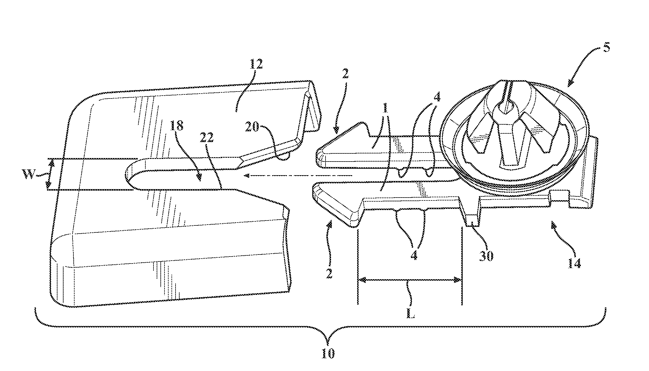
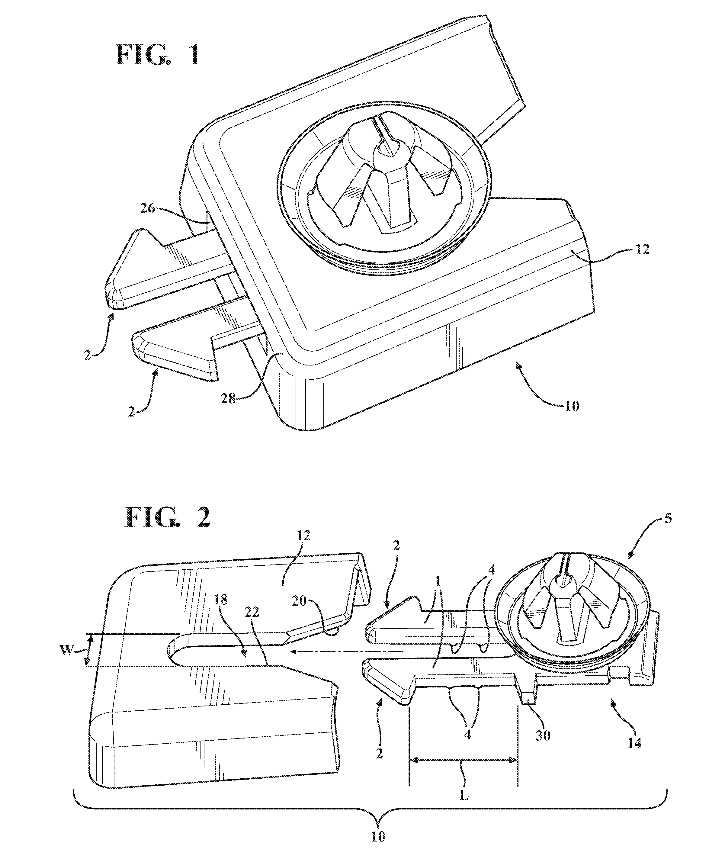
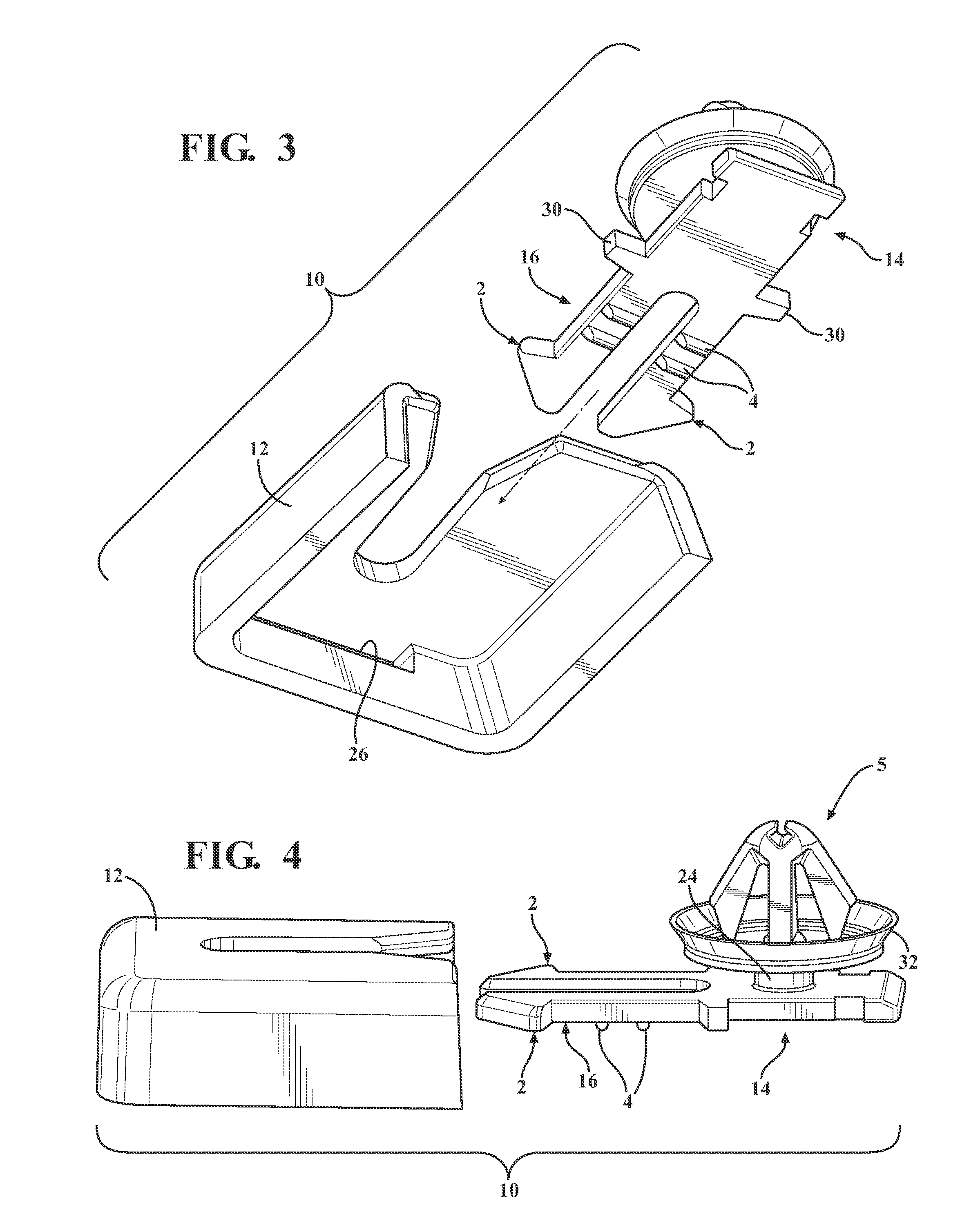
[0015]In general, the trim retention assembly of the present invention provides a clip platform that exhibits substantially consistent performance in terms of predetermined insertion and retention efforts. The clip platform is also adaptable to many different styles / setup heights of molded clips. In accordance with the present invention, it is achievable to eliminate tuning and repairs of the mold as in the case of conventional molded keyholes. There is also provided a simplified design of doghouses; the design of the doghouse is preferably standard. The present invention provides a built-in anti-rotation of the clip, as well as “float” in the clip for build tolerances and a clip centering means for nominal position. The detent features in combination with the free floating feature for tolerance variations have signif...


PUM


Abstract

A trim retainer assembly having a clip portion with a base and a molded housing having a keyhole and an opening. The keyhole in the doghouse is smooth for improved molding and elimination of tuning since there are no detents in the bore to tune or maintain. The base is provided with a pair of arms that are flexible and each arm having a self detent feature that passes through the opening in the housing to provide clip retention and, at the same time, float for tolerance variations is provided. The pair of arms also include nominal centering detents. The keyhole bore, opening, and clip portion provides clip detent, consistent retention effort, float, centering and anti-rotation.

Description

CROSS-REFERENCE TO RELATED APPLICATIONS[0001]This application claims the benefit of U.S. Provisional Application No. 62 / 077,445, filed Nov. 10, 2014. The disclosure of the above application is incorporated herein by reference.FIELD OF THE INVENTION[0002]The present invention relates to a clip assembly with detent, float and retention features for use in automotive trim attachment applications.BACKGROUND OF THE INVENTION[0003]Plastic molded clips generally are used in automotive trim panels to provide the attachment of the trim pieces or panels to the support structure of the vehicle. Known clips typically have a built-in means of detent to provide retention, however, the clips do not provide a simultaneous means for “float” tolerance variation. The trim panels have housings known as “doghouses” provided with clip keyholes to receive and retain the clip. There is poor clip retention in the molded clip positions (within the doghouses) having retainer detents (clip keyholes). This is p...

Claims


Application Information

Patent Timeline
Patent Type & Authority Applications(United States)
IPC IPC(8): B60R13/02F16B2/22
CPCF16B2/22B60R13/02B60R13/0206F16B21/08F16B5/0657F16B5/0628
Inventor BACHELDER, THEODORE J.ANDOR, RONALD J.ANDOR, MOLLI J.GIGNILLIAT, MICHAEL S.
Owner MAGNA INTERNATIONAL INC
Why Eureka
Try Eureka