Aircraft with a wing tip comprising a fuel pod

Active Publication Date: 2016-05-12
AIRBUS OPERATIONS LTD
View PDF1 Cites 10 Cited by
  • Summary
  • Abstract
  • Description
  • Claims
  • Application Information

AI Technical Summary

Benefits of technology

This patent is for a new wing design that can be used in two different configurations, allowing for easy modification of the aircraft's performance. By simply changing the wing tip, the same basic aircraft can be used with either the first or second configuration. Additionally, the wing design allows for an increased range of the aircraft while maintaining the same payload.

Problems solved by technology

Where the extra capacity of the fuel pod is not required (e.g. for shorter range mission profiles) the aircraft performance is sub-optimal because there remains a drag and weight penalty from the fuel pod, and unnecessary structural margins in the wing.
This restricts the commercial feasibility of regularly running an aircraft with permanent wing tip fuel pods, over a range of different mission profiles.
These fuel pods can be used to extend the range of an aircraft for particular mission profiles, but are unsuitable for use on commercial passenger aircraft.
Furthermore, the wings of such aircraft are typically designed for use without the drop tank, and therefore have relatively poor performance with the tank fitted.
This restricts the commercial feasibility of regularly running an aircraft with such wing tip fuel pods fitted.

Method used


Image

  • Aircraft with a wing tip comprising a fuel pod
  • Aircraft with a wing tip comprising a fuel pod
  • Aircraft with a wing tip comprising a fuel pod

Examples


Embodiment Construction

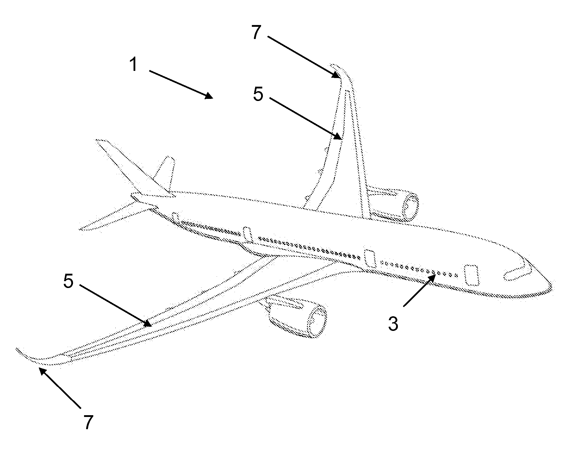
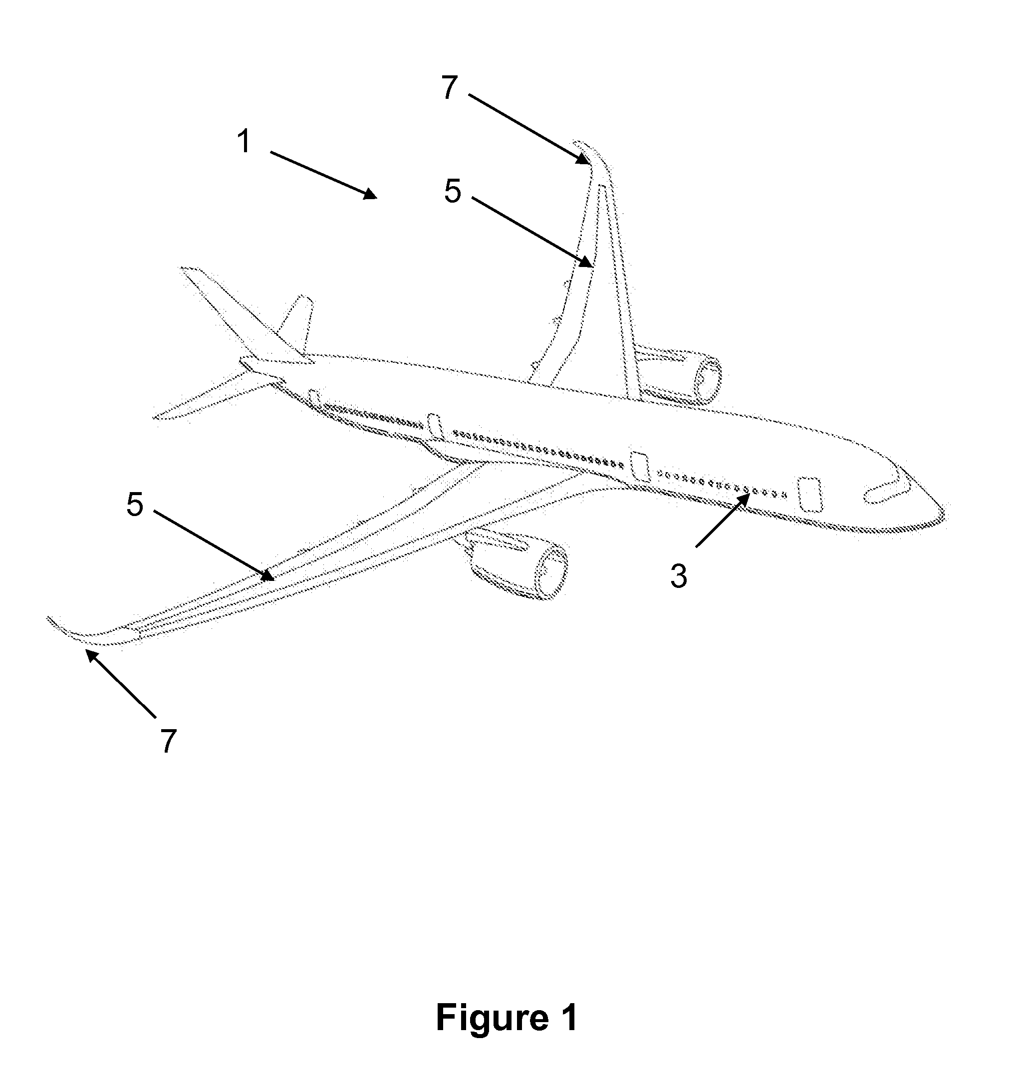
[0036]FIG. 1 shows a passenger aircraft 1 according to a first embodiment of the invention. The aircraft 1 comprises a fuselage 3 and wings 5. The aircraft is shown with its wings in a first configuration in which a winglet 7 is mounted on the end of the wing.

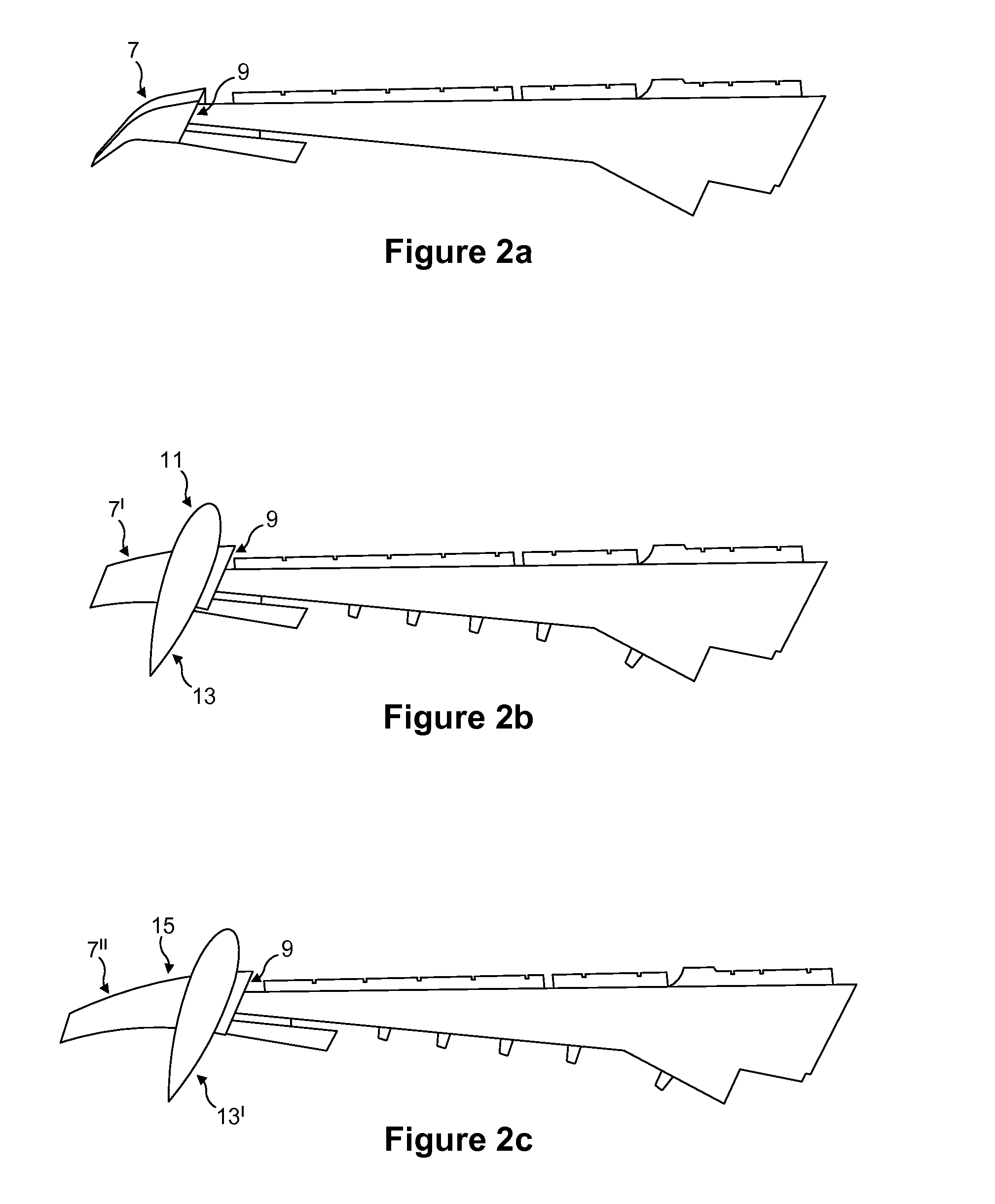
[0037]The winglet 7 attaches to its respective wing 5 at a wing-box-to-wing-tip connection interface 9 (not visible in FIG. 1 but see FIGS. 2a to 2c). In the first embodiment of the invention, the connection interface 9 is arranged to receive three different wing tips: firstly, the winglet 7 in FIGS. 1 and 2a, secondly a wing tip 11 comprising the combination of fuel pod 13 and winglet 7′ in FIG. 2b, and thirdly a wing tip 15 comprising the combination of fuel pod 13′ and (another) winglet 7″ in FIG. 2c. The structure of the wing tips and the related advantages will now be described in more detail with reference to FIGS. 2a to 4.

[0038]FIGS. 2a to 2c are schematics showing part of a wing 5 of the aircraft in FIG. 1 in three diff...


PUM


Abstract

An aircraft comprising a wing, the wing having a connection interface at the tip of the wing, and the wing being interchangeable between a first configuration in which a first wing tip is connected to the connection interface, and a second configuration in which a second wing tip is connected to the connection interface to replace the first wing tip. The second wing tip comprises a fuel pod for carrying additional fuel, and a wing tip device for improving aerodynamic efficiency. The wing may be designed for performance in both configurations.

Description

BACKGROUND OF THE INVENTION[0001]The present invention relates to aircraft and aircraft wings, and more particularly to aircraft with wings for receiving a wing tip comprising a fuel pod, and to methods of designing such wings.[0002]It has been recognised that it may be desirable for aircraft to be able to efficiently operate over a variety of different mission profiles. For example, it may be desirable for an airline to be able to operate a passenger aircraft over a first mission profile having a short range for part of a year (for example the summer), but to also be able to operate the aircraft over a second mission profile having a medium (i.e. longer) range for another part of the year (for example the winter).[0003]To increase the range of an aircraft it is usually necessary to increase the fuel capacity.[0004]It is known to provide fuel capacity by locating permanent fuel pods on aircraft wing tips. For example GB 1087784 discloses an aircraft having wing tip pods. Furthermore...

Claims


Application Information

Patent Timeline
IPC IPC(8): B64D37/04G06Q10/06G06Q30/06B64C3/38B64C23/06
CPCB64D37/04B64C3/38G06Q10/06313G06Q30/0621B64C23/065B64C23/069B64C3/34Y02T50/10B64C3/00
Inventor LAGUIA-BARNOLA, ROGERORCHARD, MATTHEW NOELWOOD, NORMAN
Owner AIRBUS OPERATIONS LTD
Why Eureka
Try Eureka