Gripping element suitable for use with an accumulator table, accumulator table provided with such a gripping element and conveyor system comprising such an accumulator table

a technology of gripping element and accumulator table, which is applied in the direction of conveyor parts, mechanical conveyors, storage devices, etc., can solve the problems of reducing the chance of product destabilization after release, the force with which the product may be hit, etc., and achieves the effect of increasing the mechanical reliability of the accumulator table, reducing the height, and being easy to apply

Active Publication Date: 2016-05-12
POLYKETTING HLDG
View PDF0 Cites 7 Cited by
  • Summary
  • Abstract
  • Description
  • Claims
  • Application Information

AI Technical Summary

Benefits of technology

[0026]Another embodiment relates to an aforementioned accumulator table, comprising multiple storage conveyors arranged parallel to each other, and two drive shafts for driving the storage conveyors, the first of the two drive shafts during use rotating at a first speed and the second of the two drive shafts during use rotating at a. second speed, wherein the storage conveyors are each provided with a first coupling for coupling to the first shaft and a second coupling for coupling to the second shaft, such that each storage conveyor can be operated at a first speed as well as a second speed. This allows the accumulator table to be accurately configured for the required buffering speed or outfeed speed. The coupling may advantageously comprise a coupling in the form of an electromagnetic clutch.
[0027]Preferably, either the first coupling or the second coupling (or both) is provided with a protection device for protecting the coupling against leakage of the product situated on the storage conveyor. This prevents malfunctioning of the couplings and thus increases the mechanical reliability of the accumulator table.
[0028]Advantageously, the protection device may comprise a hygienic tape or belt. Such a tape or belt can be easily applied to the couplings and is relatively cheap, although in practice providing more than sufficient protection to the couplings against product spills, leakage, et cetera.
[0029]Another embodiment concerns an aforementioned accumulator table, wherein at least one of the endless carriers is driveable via a spline shaft, wherein the spline shaft extends in a direction perpendicular to a plane intersecting the endless trajectory of the respective endless carrier. The use of such a spline shaft for driving the endless carrier allows for the respective transfer device comprising the respective endless carrier to be detached easily from the spline shaft. Preferably, the transfer device can even be removed by hand, wherein the transfer device can be slid off the spline shaft. Preferably, the spline shaft is driven by a drive motor situated at the underside of the accumulator table allowing for a more compact accumulator table, as well as an accumulator table having decreased height (thus providing a better overview of the table). Furthermore, configuring one or more of the transfer devices to be easily exchangeable allows fur transfer devices having a different geometry, especially a different outer, circumferential geometry to be installed relatively quickly. This feature is especially useful when products having a different width are to be processed. Preferably, in particular the inner transfer device or inner satellite, i.e. the transfer device at the inside of the transfer trajectory, is provided with such a quick change-out function. in the latter case, the outer satellite can remain in place, if required.

Problems solved by technology

In addition thereto, the orientation of the flexible fin reduces the chances of the product being destabilized after release at the release location, or at least reduces the force with which the product may be hit at the release location.

Method used


Image

  • Gripping element suitable for use with an accumulator table, accumulator table provided with such a gripping element and conveyor system comprising such an accumulator table
  • Gripping element suitable for use with an accumulator table, accumulator table provided with such a gripping element and conveyor system comprising such an accumulator table
  • Gripping element suitable for use with an accumulator table, accumulator table provided with such a gripping element and conveyor system comprising such an accumulator table

Examples


Embodiment Construction

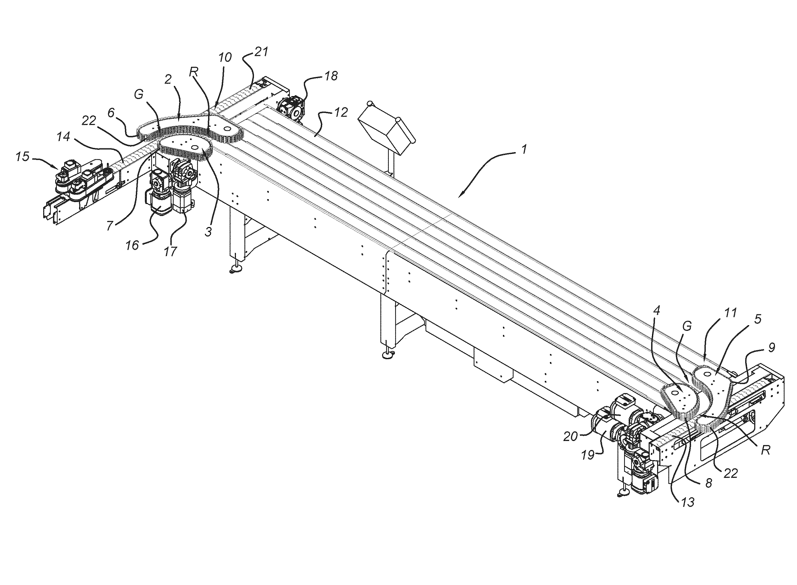
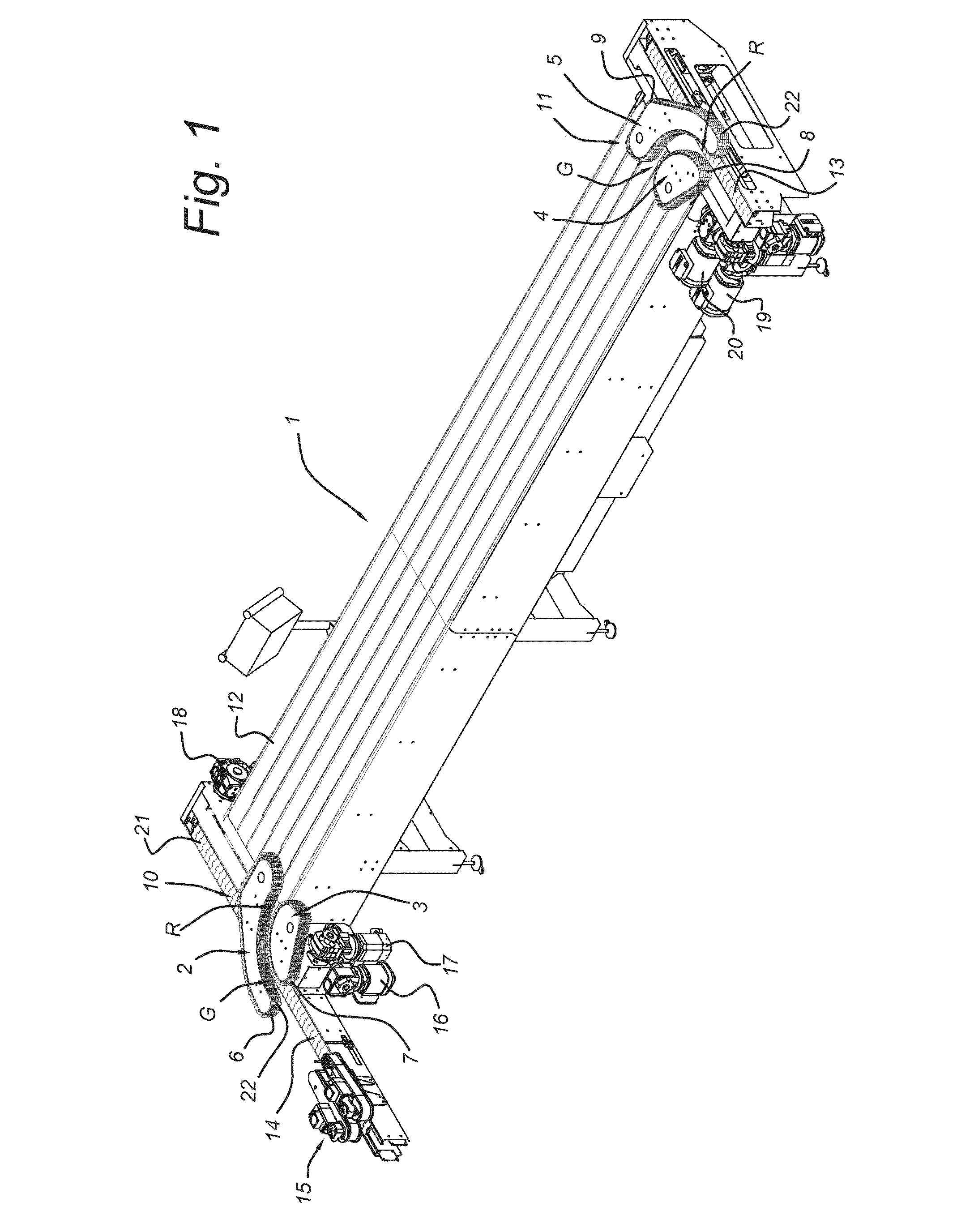
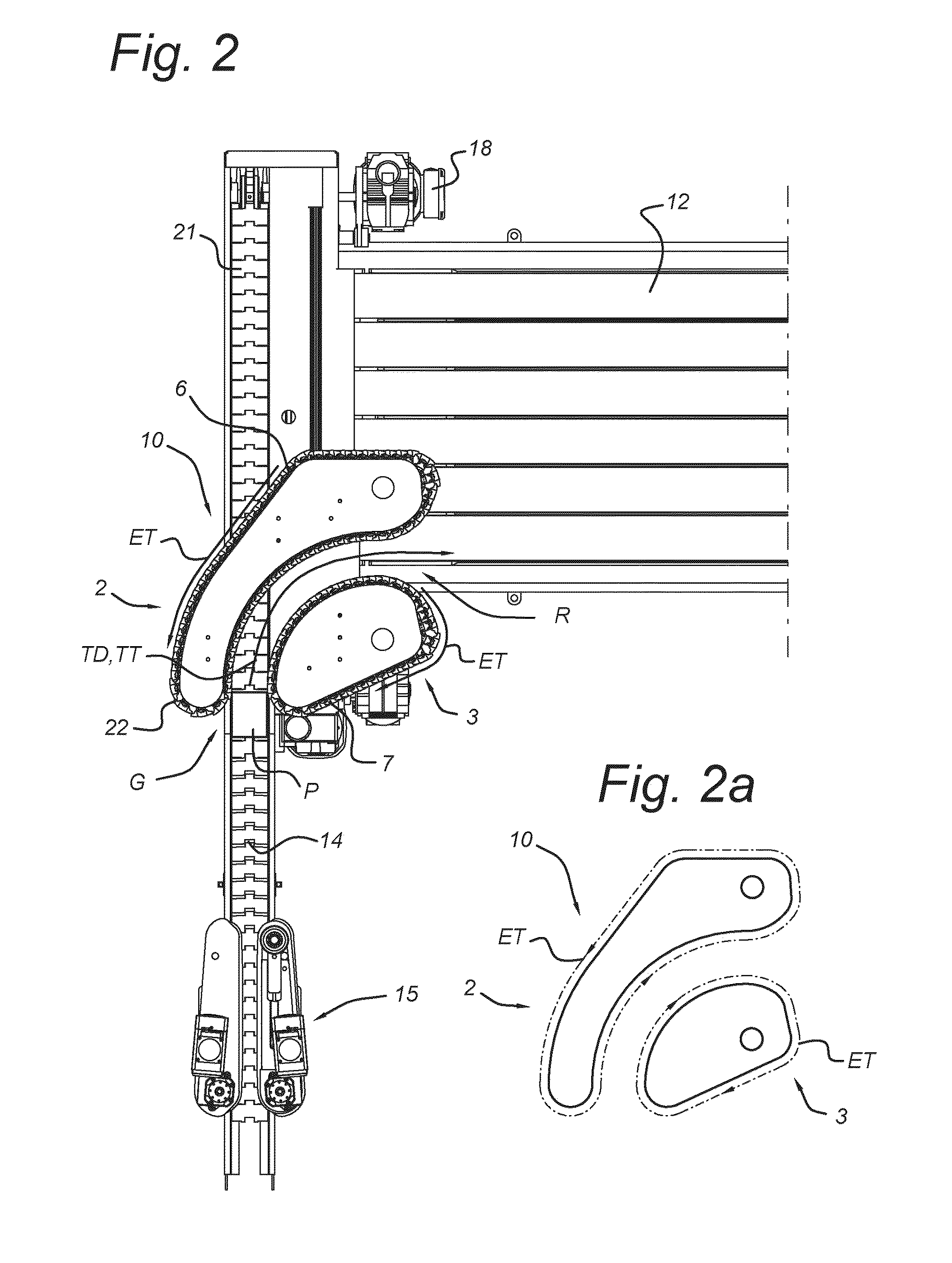
[0037]FIG. 1 shows a perspective view of an exemplary embodiment of an accumulator table 1 according to the invention, for use in a conveyor system. On the left side of FIG. 1, the accumulator table 1 comprises a first transfer arrangement 10 with a first transfer device 2 and a second, opposing transfer device 3, thereby forming a pair of opposing transfer devices 2, 3. On the right side of FIG. 1, the accumulator table 1 comprises a similar, second transfer arrangement 11 with a third transfer device 4 and a fourth, opposing transfer device 5, forming a pair of opposing transfer devices 4, 5. In principle, one of the transfer devices can alternatively comprise a non-driven guide rail or the like, but performance and transfer accuracy will decrease then. When seen from above, the first and fourth transfer devices 2, 5 have a C-like shape, whereas the second and third transfer devices 3, 4 have the shape of a semicircle. The C-like shape essentially opposes and matches the curved pa...


PUM


Abstract

A gripping element for a transfer arrangement of an accumulator table, including a pair of opposing transfer devices for engaging a product at a gripping location on an infeed conveyor for the transfer devices and for releasing the product, the transfer devices having a driven, endless carrier including gripping elements, driven such that when the drive system is activated the gripping elements are moved by the endless carrier along an endless trajectory, the transfer devices configured for simultaneously moving all gripping elements, and the product engaged thereby, in a transfer direction along a transfer trajectory from the gripping location to a release location, includes a flexible fin for engaging the product, during use substantially extending in a plane aligned with the transfer direction, the fin having such a shape that, when at that gripping location, the transfer direction is substantially parallel to a product support surface of the infeed conveyor.

Description

FIELD OF THE INVENTION[0001]The invention relates to a gripping element, suitable for use in a transfer arrangement of an accumulator table, the transfer arrangement comprising a pair of opposing transfer devices for engaging a product at a gripping location on an infeed conveyor for the transfer devices and for releasing the product at a release location, such as on an outfeed conveyor.[0002]wherein the infeed conveyor is positioned in such a way as to deliver the product to the transfer devices of the accumulator table, wherein the transfer devices are suitable for being provided with an endless carrier comprising a plurality of gripping elements,[0003]wherein the endless carrier is to be driven by a drive system, in such a way, that when the drive system is activated the gripping elements are moved by the endless carrier along an endless trajectory,[0004]wherein the transfer devices are configured for simultaneously moving the gripping elements of both transfer devices, and the p...

Claims


Application Information

Patent Timeline
Patent Type & Authority Applications(United States)
IPC IPC(8): B65G47/51B65G37/00
CPCB65G37/005B65G47/5109B65G17/44B65G47/5104B65G47/71
Inventor HANSELMAN, MARCEL
Owner POLYKETTING HLDG
Why Eureka
Try Eureka