Centrifugal compressor with channel ring defined inlet recirculation channel

a centrifugal compressor and channel ring technology, applied in the direction of machines/engines, stators, liquid fuel engines, etc., can solve the problem of not being designed for flow efficiency, and achieve the effect of optimizing aerodynamic performance and minimizing losses

Inactive Publication Date: 2005-09-20
ELECTRO-MOTIVE DIESEL
View PDF5 Cites 28 Cited by
  • Summary
  • Abstract
  • Description
  • Claims
  • Application Information

AI Technical Summary

Benefits of technology

[0004]The present invention provides an integrated turbocharger inlet design that allows optimizing aerodynamic performance of a centrifugal compressor utilizing inlet air recirculation. Configuring the inlet components in an aerodynamic fixed configuration minimizes losses associated with prior designs of fixed geometry and costs associated with more complicated designs of variable geometry.
[0006]Use of the separate channel ring allows all surfaces of the channel to be accurately configured, by machining if required, to obtain an efficient flow channel configuration. Radial supports connecting the ring to the housing and inlet member are located near the channel inlet in an area of relatively low momentum air flow to prevent aerodynamic disturbances from adversely affecting the impeller during rotation at high speeds.

Problems solved by technology

In particular cases, air inlet recirculation has been proposed; however, the recirculation passages and the inlet and outlet slots have varied in cross-sectional area and smoothness and have not been designed for flow efficiency.

Method used


Image

  • Centrifugal compressor with channel ring defined inlet recirculation channel
  • Centrifugal compressor with channel ring defined inlet recirculation channel
  • Centrifugal compressor with channel ring defined inlet recirculation channel

Examples


Embodiment Construction

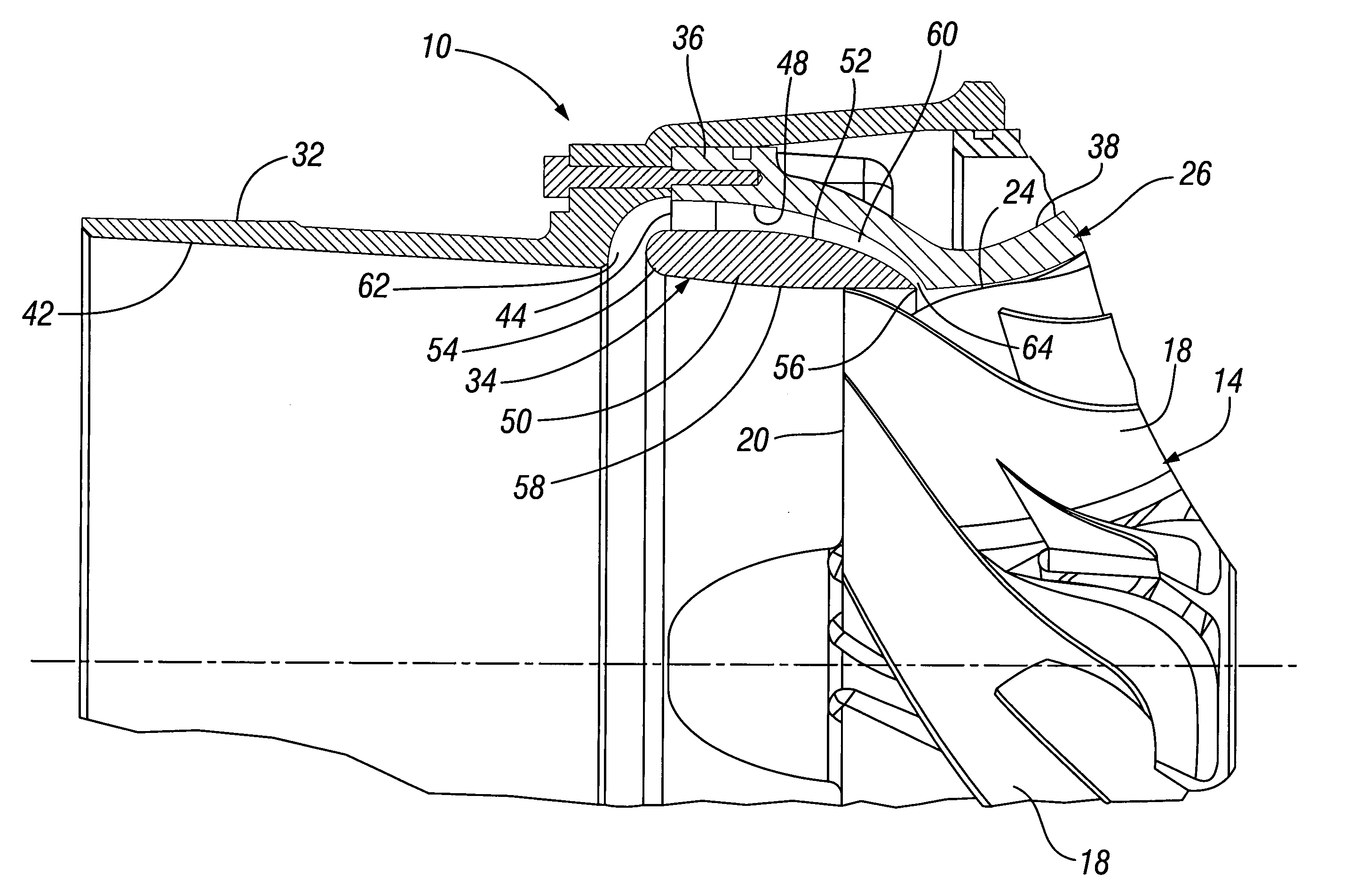
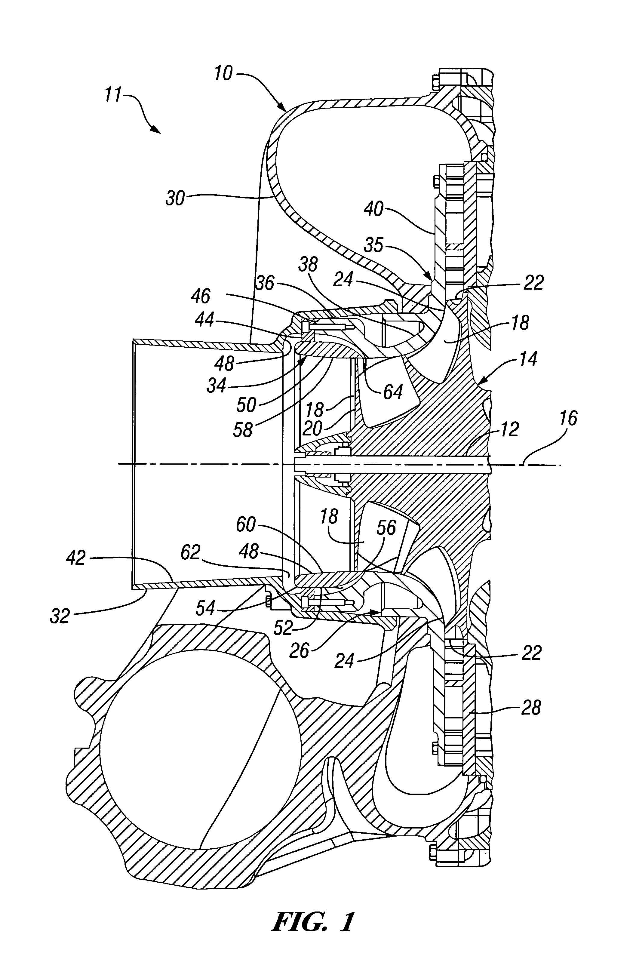
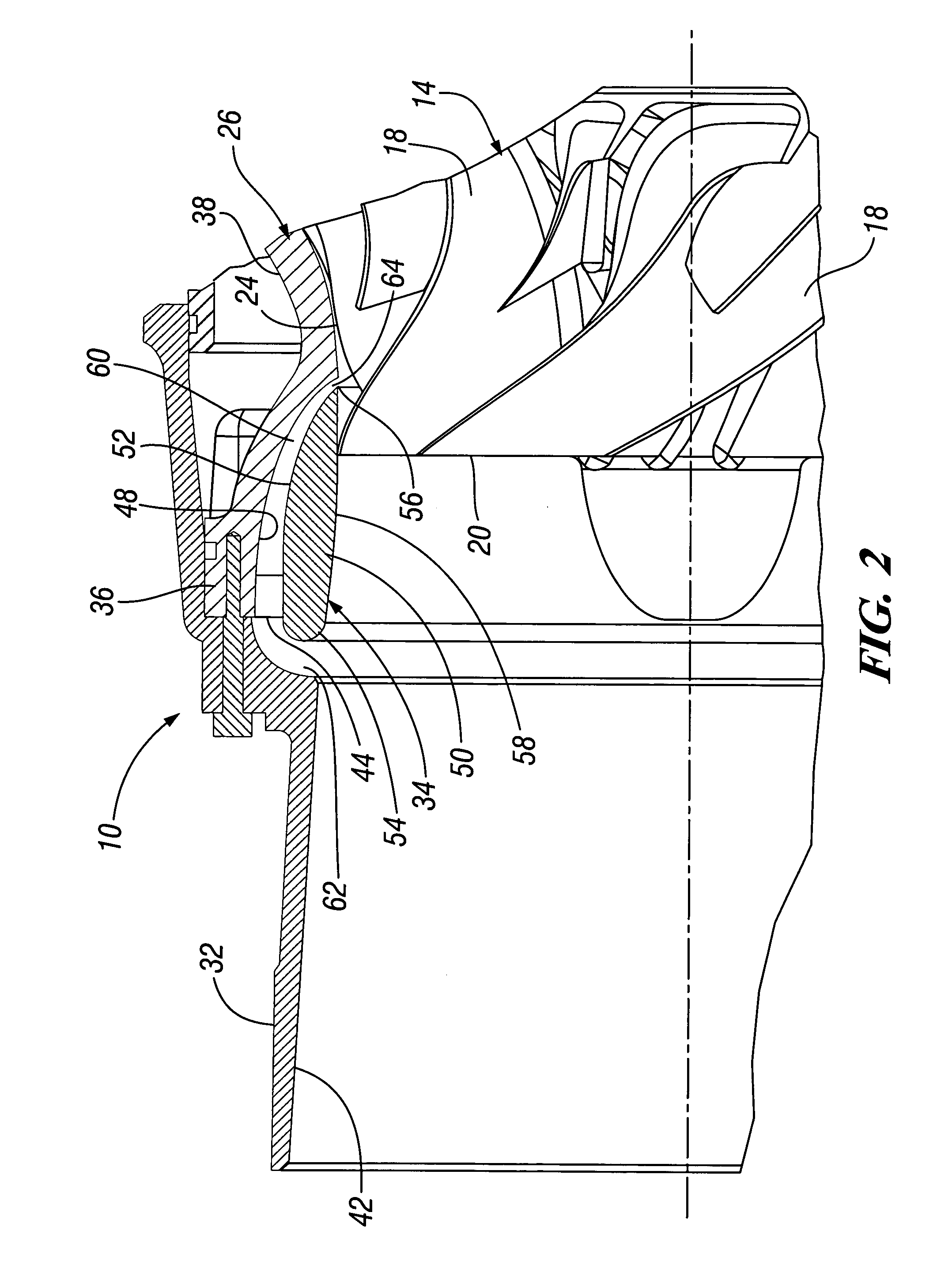
[0010]Referring now to the drawings in detail, numeral 10 generally indicates a centrifugal compressor forming a portion of an engine turbocharger 11. The turbocharger includes an exhaust driven turbine, not shown, connected with a drive shaft 12 for rotatably driving an impeller 14 of the compressor. However, the features of the invention could also apply to other centrifugal compressors whether or not connected with engines or turbochargers.

[0011]The turbine, drive shaft and impeller are fixed together for rotation on a longitudinal axis 16. The impeller 14 includes a plurality of vanes 18, each having a leading edge 20, a trailing edge 22 and an outer edge 24. The compressor 10 further includes a compressor housing 26, a diffuser 28, an outlet scroll 30, an inlet member 32 and a channel ring 34.

[0012]The compressor housing includes an annular wall 35 having an inlet portion 36, an intermediate portion 38, and an outlet portion 40 that forms a front wall for the diffuser. The outl...


PUM


Abstract

A centrifugal compressor includes an annular inlet air recirculation channel having a smoothly variable cross section extending from a first slot at a forward end of the channel adjacent an inlet member to a second slot at a rearward end of the channel beyond an inlet end of a vaned compressor impeller. The channel is formed between an aerodynamic channel ring supported in a smooth annular recess formed in a compressor housing and the separate inlet member. The ring may be mounted by radial struts connected with the housing and located in an area of low momentum air flow. The channel ring and the channel recess may be machined or otherwise formed with smoothly variable surfaces prior to assembly of the ring into the housing. The channel may have a smoothly diminishing annular cross section for aerodynamically efficient air flow.

Description

TECHNICAL FIELD[0001]This invention relates to centrifugal compressors and to a channel ring defined inlet recirculation channel for such compressors.BACKGROUND OF THE INVENTION[0002]It is known in the art relating to centrifugal compressors for air and other compressible gases that the operational range of pressure ratios of the compressor may be increased by providing bleed passages in the housing at suitable locations adjacent the impeller. This is particularly useful for engine turbocharger compressors, which are intended to operate over a wide range of rotational speeds under various conditions of engine speed, load and ambient pressure.[0003]In particular cases, air inlet recirculation has been proposed; however, the recirculation passages and the inlet and outlet slots have varied in cross-sectional area and smoothness and have not been designed for flow efficiency.SUMMARY OF THE INVENTION[0004]The present invention provides an integrated turbocharger inlet design that allows...

Claims


Application Information

Patent Timeline
Patent Type & Authority Patents(United States)
IPC IPC(8): F04D27/02F04D29/42
CPCF04D29/4213F04D29/685F04D27/0207
Inventor SVIHLA, GARY R.XIAO, XINWENCARR, JOHN M.
Owner ELECTRO-MOTIVE DIESEL
Why Eureka
Try Eureka