Method for operating a device for conveying a liquid

Active Publication Date: 2016-05-12
VITESCO TECH GMBH
View PDF6 Cites 8 Cited by
  • Summary
  • Abstract
  • Description
  • Claims
  • Application Information

AI Technical Summary

Benefits of technology

[0008]An object of the present invention is to solve, or at least lessen, the technical problems discussed above. It is sought in particular to propose a particularly

Problems solved by technology

This volume expansion can damage the device for delivering the liquid.
Accordingly, it is also not possible for any volume expansion of the liquid to occur within the device.
It is, however, a problem that an evacuated device must be refilled before a resumption of op

Method used


Image

  • Method for operating a device for conveying a liquid
  • Method for operating a device for conveying a liquid
  • Method for operating a device for conveying a liquid

Examples


Embodiment Construction

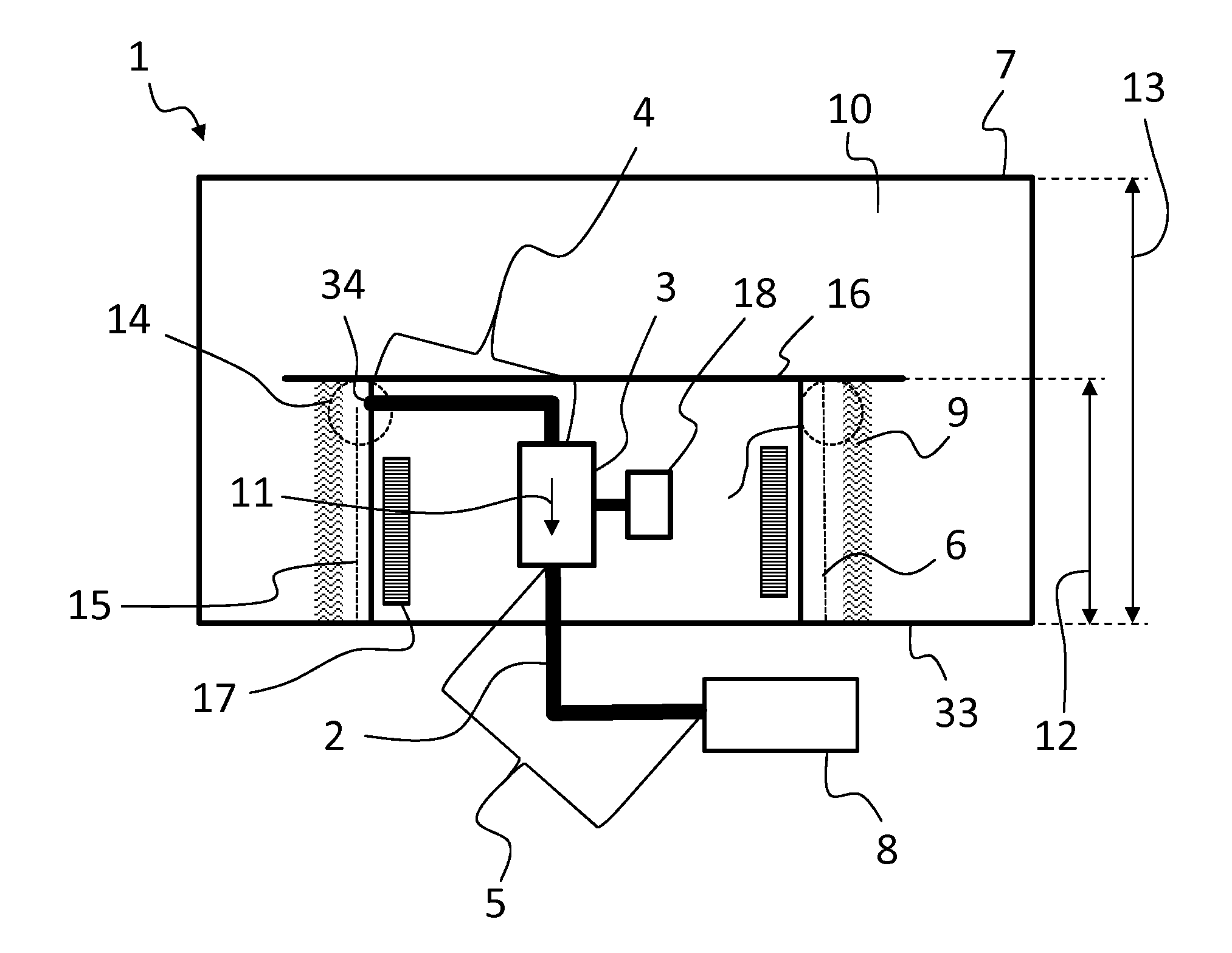
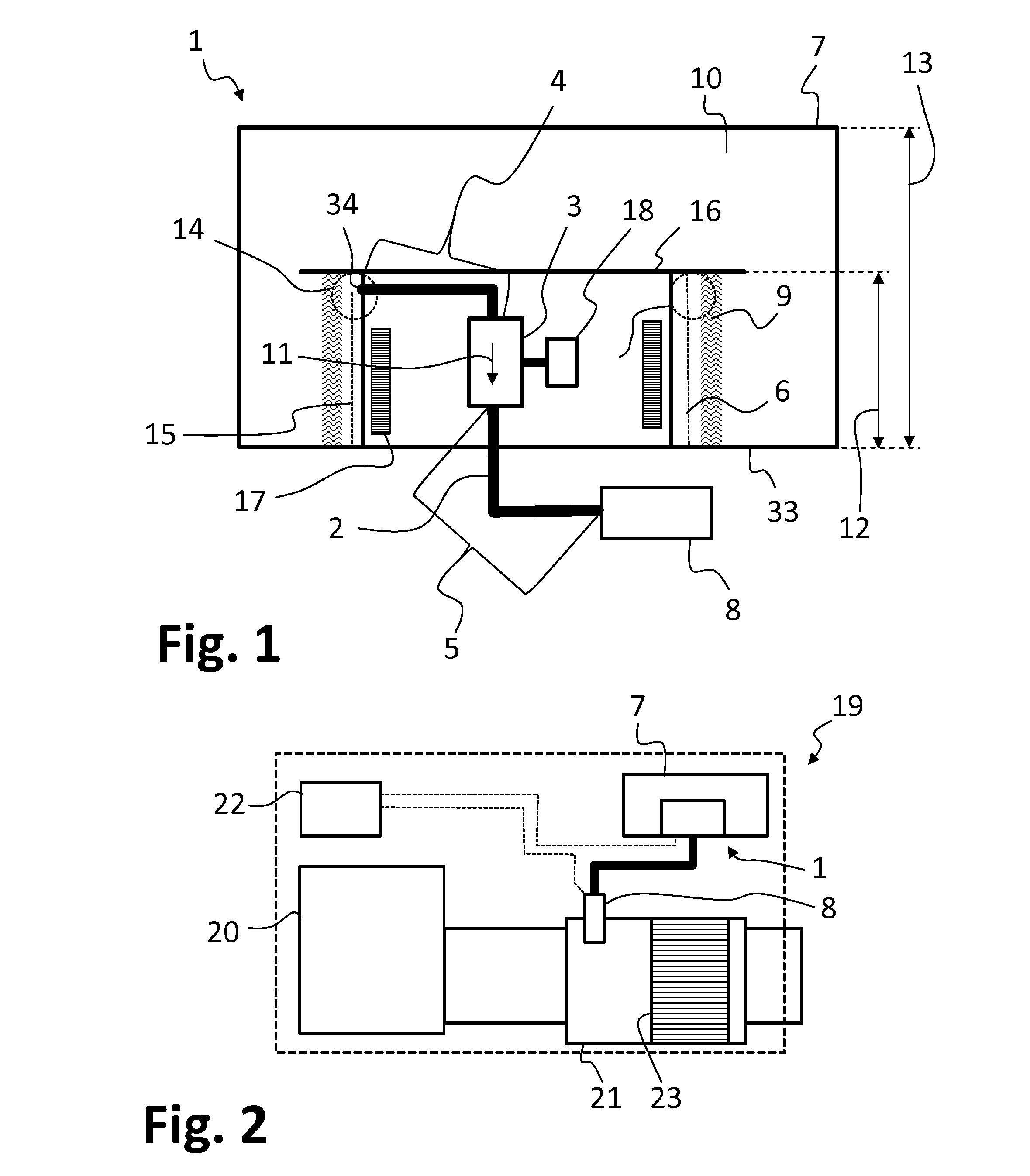
[0047]FIG. 1 illustrates a first design variant of a device 1 which can be evacuated in accordance with the described method. The device 1 comprises a tank 7, in the interior 10 of that the liquid (in particular an aqueous urea-water solution) is stored. In the tank 7 there is arranged a housing 16 which extends into the interior 10 of the tank 7 from the tank base 33. The tank 7 has a height 13. The housing 16 extends over a portion 12 of the height 13 of the tank 7. The filter space 6 is formed as an encircling jacket 15 around the housing 16. The filter space 6 is separated from the interior 10 of the tank 7 by a filter layer 9. A heater 17 is arranged in the housing 16. The heater 17 is designed to supply heat through the filter space 6 and the filter layer 9 to liquid stored in the interior 10 of the tank 7. For this purpose, it is provided that the filter space 6 is filled with liquid in order to realize good thermal conductivity through the filter space 6.

[0048]In the housing...


PUM


Abstract

A method for operating a device configured to deliver a liquid includes: a) back-suctioning a liquid situated in a pressure line section counter to a usual delivery direction by at least one pump; b) monitoring at least one operating parameter of the at least one pump during the back-suctioning, the at least one operating parameter being representative of a counterpressure that the at least one pump operates against during the back-suctioning; and c) detecting an increase in the counterpressure, and stopping the back-suctioning.

Description

CROSS-REFERENCE TO RELATED APPLICATIONS[0001]This is a U.S. national stage of application No. PCT / EP2014 / 059515, filed on 9 May 2014, which claims priority to the German Application No. DE 10 2013 105 712.8 filed 4 Jun. 2013, the content of both incorporated herein by reference.BACKGROUND OF THE INVENTION[0002]1. Field of the Invention[0003]The invention relates to a method for operating a device for delivering a liquid, in particular for the evacuation thereof. The device may be used for example in a motor vehicle in order to deliver a liquid additive to an exhaust-gas treatment device for the purification of the exhaust gases of an internal combustion engine of the motor vehicle, and to feed the liquid additive to the exhaust-gas treatment device in dosed fashion.[0004]2. Related Art[0005]In exhaust-gas treatment devices to which a liquid additive for exhaust-gas purification is fed, the method of selective catalytic reduction (SCR), for example, is implemented. In the method, nit...

Claims


Application Information

Patent Timeline
IPC IPC(8): F01N3/20
CPCF01N3/208F01N2900/1822F01N2900/1808F01N2900/0414B60K13/04B60K2015/03427F01N3/2066F01N2610/02F01N2610/1426F01N2610/144F01N2610/1486F01N2610/1493Y02T10/12Y02A50/20
Inventor BRUCK, ROLFHODGSON, JANVORSMANN, CHRISTIAN
Owner VITESCO TECH GMBH
Why Eureka
Try Eureka