
Display panel

a display panel and panel technology, applied in the field of display panels, can solve the problems of deteriorating display effect, unable to meet the requirement for high-resolution display products, unable to further reduce the size of the sub-pixel b>1/b> of the conventional display panel, etc., to achieve the effect of reducing parasitic capacitance, improving display quality, and reducing aperture ratio

Active Publication Date: 2016-05-12
AU OPTRONICS CORP
View PDF0 Cites 11 Cited by
  • Summary
  • Abstract
  • Description
  • Claims
  • Application Information

AI Technical Summary

Benefits of technology

[0006]In one aspect, a display device with high aperture ratio and low parasitic capacitance is provided.
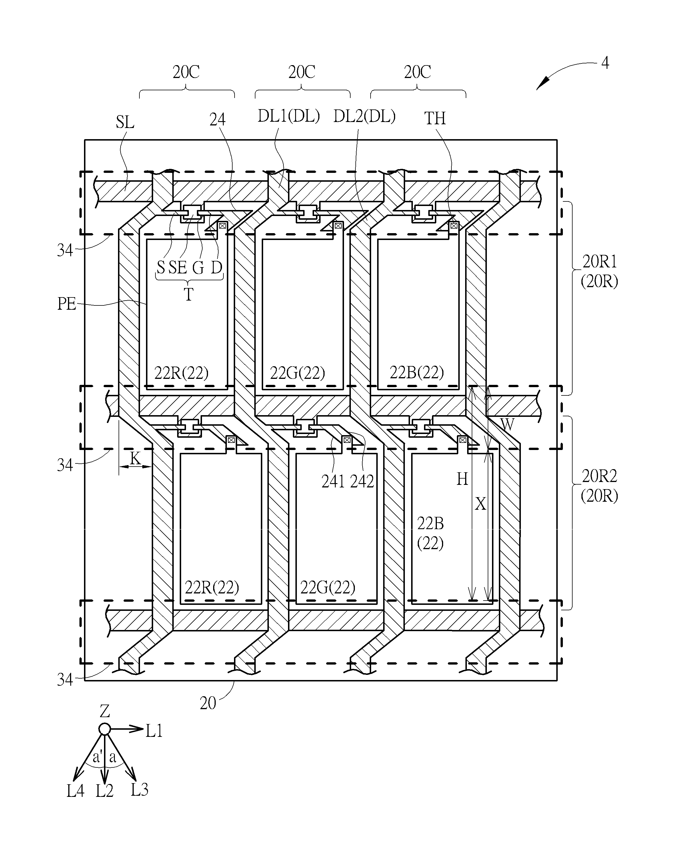
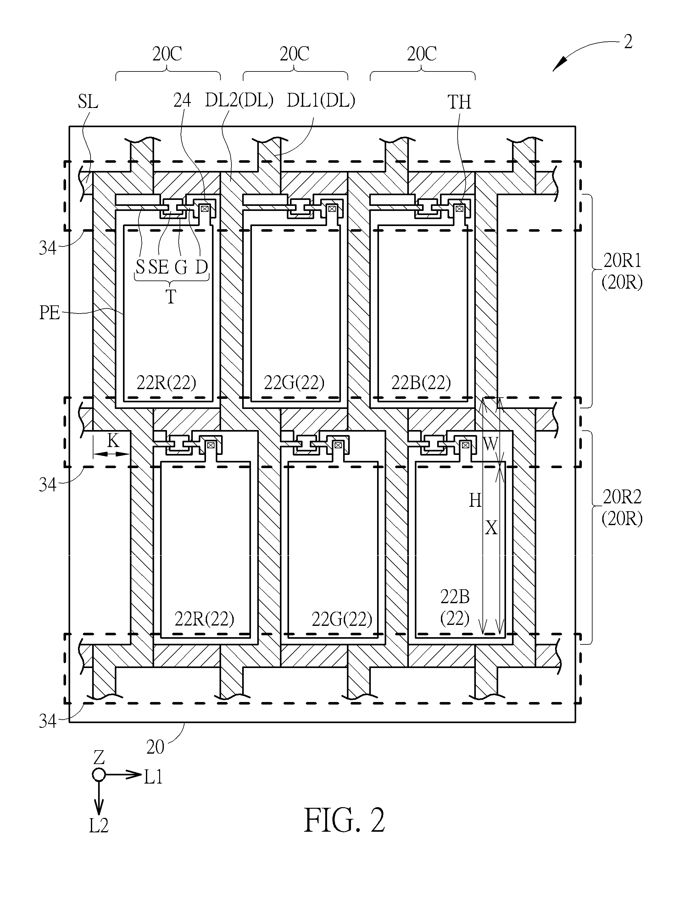
[0008]The staggered arrangement between the sub-pixels of two adjacent rows is able to avoid light halo phenomenon when displaying high frequency zone of circular zone plate (CPZ) pattern and avoid color deviation (color shift) problem. In addition, the obliquely-disposed second data segment is able to reduce the parasitic capacitance between the data line and the scanning line while the aperture ratio is unaffected or even increased. Accordingly, the display quality is improved.

Problems solved by technology

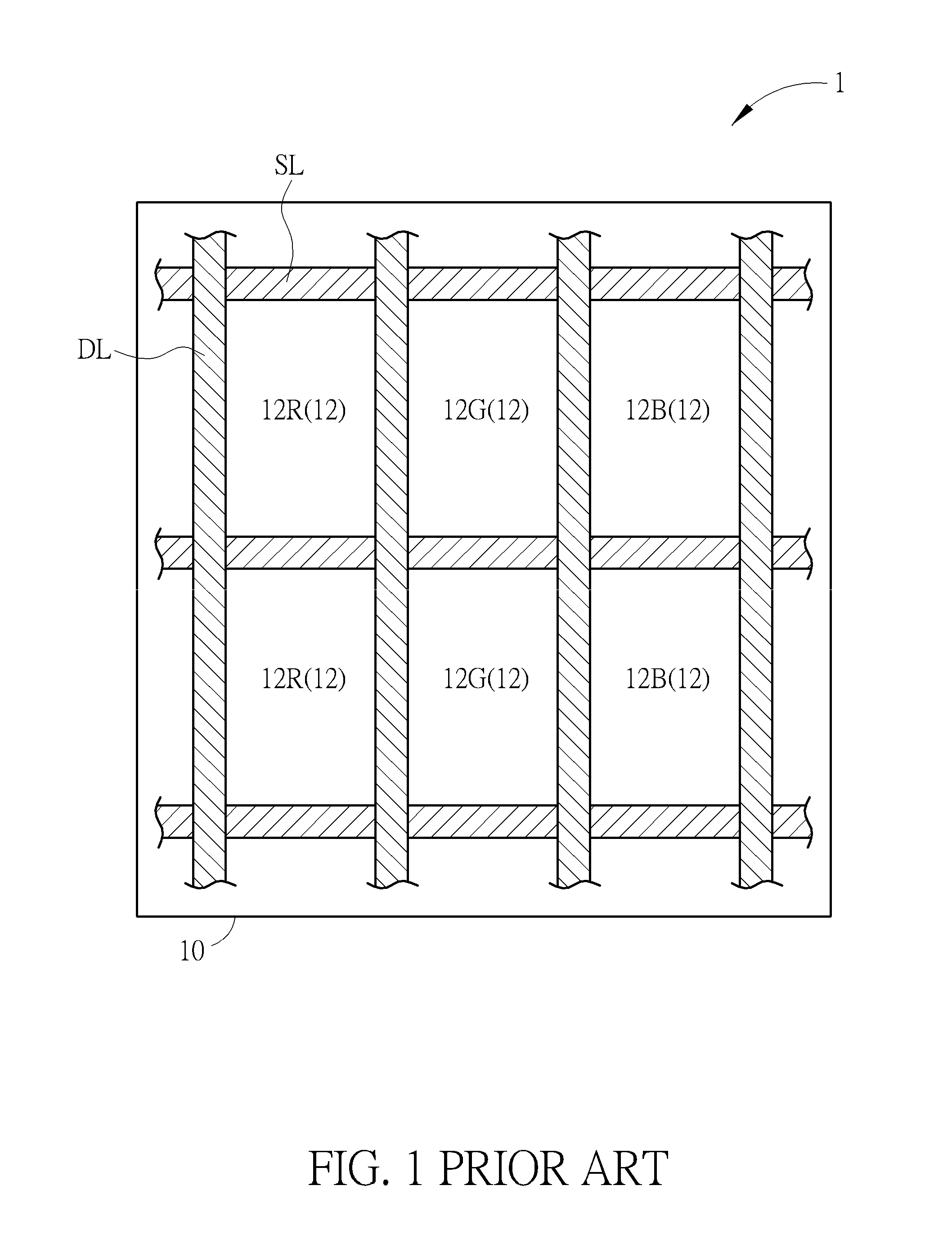
The size of the sub-pixel 12 of the conventional display panel 1, however, cannot be further reduced based on current process limit and design rule, which is no longer able to meet the requirement for high resolution display products.
Most importantly, color deviation i.e. color shift will occur when light halo phenomenon gets serious, which deteriorates display effect.

Method used


Image

  • Display panel
  • Display panel
  • Display panel

Examples


Embodiment Construction

[0015]To provide a better understanding of the disclosure to the skilled users in the technology of the disclosure, exemplary embodiments will be detailed as follows. The exemplary embodiments of the disclosure are illustrated in the accompanying drawings with numbered elements to elaborate the contents and effects to be achieved.

[0016]Referring to FIGS. 2-3, FIG. 2 is a top view diagram illustrating a display panel according to a first exemplary embodiment, and FIG. 3 is a cross-sectional view illustrating a display panel according to a first exemplary embodiment. As shown in FIGS. 2-3, the display panel 2 of this exemplary embodiment includes a first substrate 20, a plurality of scanning lines (also referred to as gate lines), a plurality of data lines DL, a second substrate 30 and a display medium layer 32. The first substrate 20 may include a transparent substrate e.g. a glass substrate, a plastic substrate or a quartz substrate, but not limited thereto. The first substrate 20 m...


PUM


Abstract

A display panel includes a plurality of sub-pixels, scanning lines and data lines. The sub-pixels are disposed on a first substrate and include a plurality of rows and columns, and each sub-pixel of a first row of two adjoining rows is shifted by a predetermined distance along a first direction with respect to each sub-pixel of a second row of two adjoining rows. The scanning lines extend in the first direction and corresponding to the sub-pixels of the rows respectively. Each data line includes a plurality of first data segments and second data segments connected alternately. The first data segment extends along a second direction and partially overlaps the scanning line in a vertical direction. Each second data segment is disposed on one side of the scanning line, and at least a portion of the second data segments extends along a third direction different from the first and second directions.

Description

BACKGROUND OF THE DISCLOSURE[0001]1. Field of the Disclosure[0002]The present disclosure is related to a display panel, and more particularly, to a display panel with high aperture ratio and low parasitic capacitance.[0003]2. Background of the Disclosure[0004]Referring to FIG. 1, FIG. 1 is a schematic diagram illustrating a conventional display panel. As shown in FIG. 1, the conventional display panel 1 includes a substrate 10, and a plurality of scanning lines SL and data lines DL disposed on the substrate 10 defining a plurality of sub-pixels 12. The sub-pixels 12 are arranged in a stripe pattern including a plurality of rows and columns. The sub-pixels 12 includes a plurality of red sub-pixels 12R, green sub-pixels 12G and blue sub-pixels 12B, where the red sub-pixels 12R, the green sub-pixels 12G and the blue sub-pixels 12B are repeatedly arranged in order in the row direction, and the sub-pixels 12 of the same column have the same color. For example, the sub-pixels 12 of the fi...

Claims


Application Information

Patent Timeline
Patent Type & Authority Applications(United States)
IPC IPC(8): G09G3/20
CPCG09G3/2003G09G2320/02G09G2300/0465G02F1/136209G02F1/136286G02F1/1368G02F1/136222G02F1/134336
Inventor TSAI, AI-JULEE, MING-HSIEN
Owner AU OPTRONICS CORP
Learn More