Organic lighting element color pixel array mode and its forming method

A pixel and element technology, applied in the field of color display panels, can solve the problems of mask etching manufacturing difficulties, difficulty in manufacturing high-resolution OLED displays, misalignment and other problems

Inactive Publication Date: 2007-10-10
AU OPTRONICS CORP
View PDF0 Cites 68 Cited by
  • Summary
  • Abstract
  • Description
  • Claims
  • Application Information

AI Technical Summary

Problems solved by technology

In this way, the sub-pixel elements of the OLED display panel are likely to be misaligned in the row direction, and the organic layers of each color in the sub-pixel are deposited in other sub-pixels, resulting in color mixing or color mixing of the light emitted by each sub-pixel element. The problem that the upper and lower electrodes in each two adjacent sub-pixel elements are short-circuited and do not emit light
The arrangement of sub-pixel elements also makes the corresponding mask quite difficult in etching and manufacturing. Therefore, it will be difficult to manufacture high-resolution OLED displays using the traditional arrangement of sub-pixel elements.

Method used


Image

  • Organic lighting element color pixel array mode and its forming method
  • Organic lighting element color pixel array mode and its forming method
  • Organic lighting element color pixel array mode and its forming method

Examples


Embodiment Construction

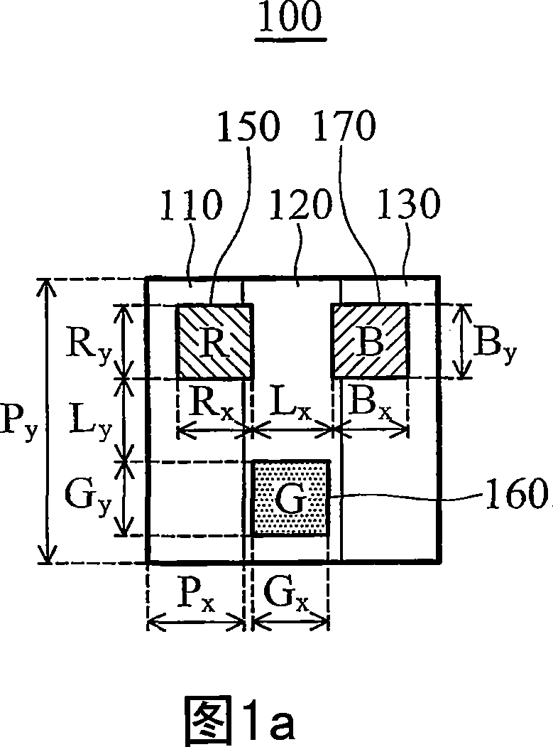
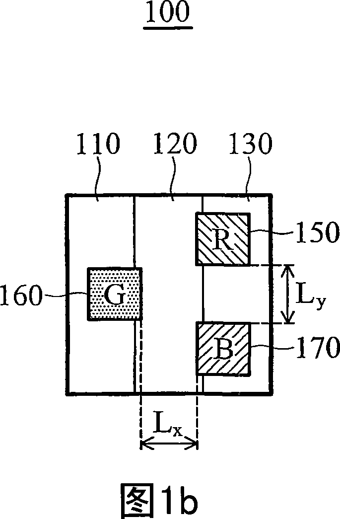
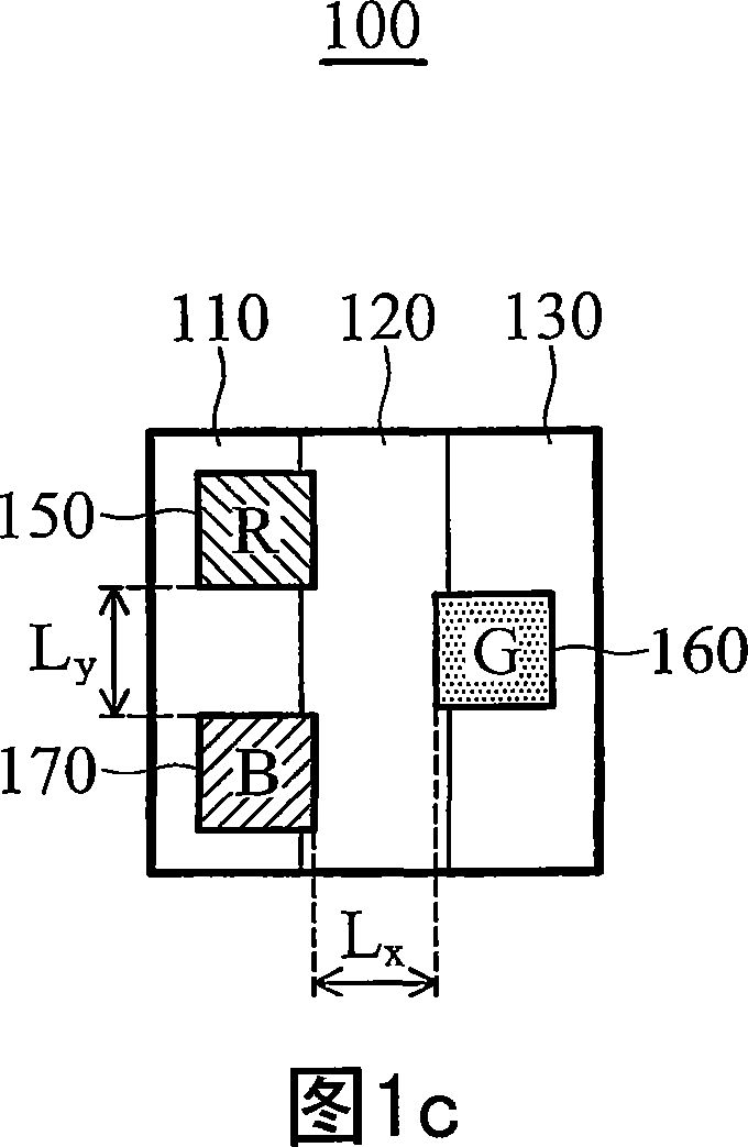
[0069] The full-color display panel of the present invention has a plurality of pixels arranged in a matrix in a row direction and a column direction perpendicular to the row direction. Referring to FIGS. 1 a to 1 c , each pixel 100 includes a first sub-pixel 110 , a second sub-pixel 120 and a third sub-pixel 130 , which are adjacent to each other and arranged along the row direction of the pixel matrix. Each sub-pixel ( 110 , 120 , 130 ) is substantially equal, and has a sub-pixel pitch Px in a row direction and a sub-pixel pitch Py in a column direction. The sub-pixel pitch Px in the row direction and the sub-pixel pitch Py in the column direction together define the sub-pixel area, that is, (Px×Py).

[0070] In addition, each pixel 100 has a red (sub-pixel) light-emitting area 150, a green (sub-pixel) light-emitting area 160 and a blue (sub-pixel) light-emitting area 170, which are arranged in a triangle, and each sub-pixel light-emitting area ( 150, 160, 170) have their g...


PUM


Abstract

A color display panel has an array with a plurality of pixels, each pixel comprises a first sub pixel, a second sub pixel and a third sub pixel, and a red luminescence zone, green luminescence zone and blue luminescence zone. The display panel comprises pixel arrangement of the red luminescence zone, green luminescence zone and blue luminescence zone, which forms a triangle, geometry center of each luminescence zone is positioned at different vertexes of the triangle, such that a side of the triangle substantially is in parallel with on of row direction and column direction, arbitrary luminescence zones bothering with different colors of the row direction are defined to have a distance gap, and arbitrary luminescence zones bothering with different colors of the column direction are defined to have a distance gap, the two gaps distance is substantially or almost equal. The invention can reduce the contraposition difficulty of mask manufacturing technique, besides can increase the opening ratio of the luminescence area of sub pixel, to avoid the color blending circumstance of full color OLED display panel.

Description

technical field [0001] The invention relates to a color display panel, in particular to a sub-pixel arrangement design of an organic light-emitting display element. Background technique [0002] Generally speaking, a full-color display panel is composed of sub-pixel elements such as red, green, and blue. Traditionally, it refers to the design structure of a liquid crystal display in a stripe, mosaic, or delta type. Arrangement to provide a full-color effect by mixing the light of each color emitted from different sub-pixel elements in the display panel. Due to the advantages of light and thin size, high resolution, low power consumption, self-luminescence and fast response, organic light emitting diode (OLED) display panels have been gradually applied to high-definition displays of full-color images. [0003] Traditionally, the arrangement of red, green and blue sub-pixel elements of a liquid crystal display is applied to an OLED display panel, as shown in FIG. 6 . In this...

Claims


Application Information

Patent Timeline
Patent Type & Authority Applications(China)
IPC IPC(8): H01L27/32H01L21/82
CPCH01L27/3211H01L27/3218H10K59/352H10K59/353
Inventor 赵清烟吴元均
Owner AU OPTRONICS CORP
Why Eureka
Try Eureka