Connection structure of crimp terminal with respect to wire

Active Publication Date: 2016-05-19
YAZAKI CORP
View PDF33 Cites 4 Cited by
  • Summary
  • Abstract
  • Description
  • Claims
  • Application Information

AI Technical Summary

Benefits of technology

The present invention aims to provide a connection structure for a crimp terminal and wire that ensures reliable waterproof performance without requiring extra man-hour. The invention achieves this by eliminating the need for a crushing process after the caulking process and reducing processing costs. Additionally, the invention allows for easy determination of waterproof performance.

Problems solved by technology

That is, galvanic corrosion occurs.
However, in the connection structure of the crimp terminal with respect to the wire of the related art described in JP-A-2013-80682, a crushing and closing process of the front end of the wire connection section 120 is necessary after the caulking pieces 126 and 127 caulk round inwardly with respect to the end portion of the wire W. There is a problem that man-hours and processing costs are increased, accordingly.
Furthermore, since presence or absence or an assembled state of the waterproof sheet 130 cannot be confirmed from the outside after crimping, there is a problem that determining the guarantee of waterproof performance is difficult.
Therefore, even if the crimp terminal is configured of different kinds of metals with respect to the conductor of the wire, the electrolytic solution is not supplied between the different kinds of metals.

Method used


Image

  • Connection structure of crimp terminal with respect to wire
  • Connection structure of crimp terminal with respect to wire
  • Connection structure of crimp terminal with respect to wire

Examples


first embodiment

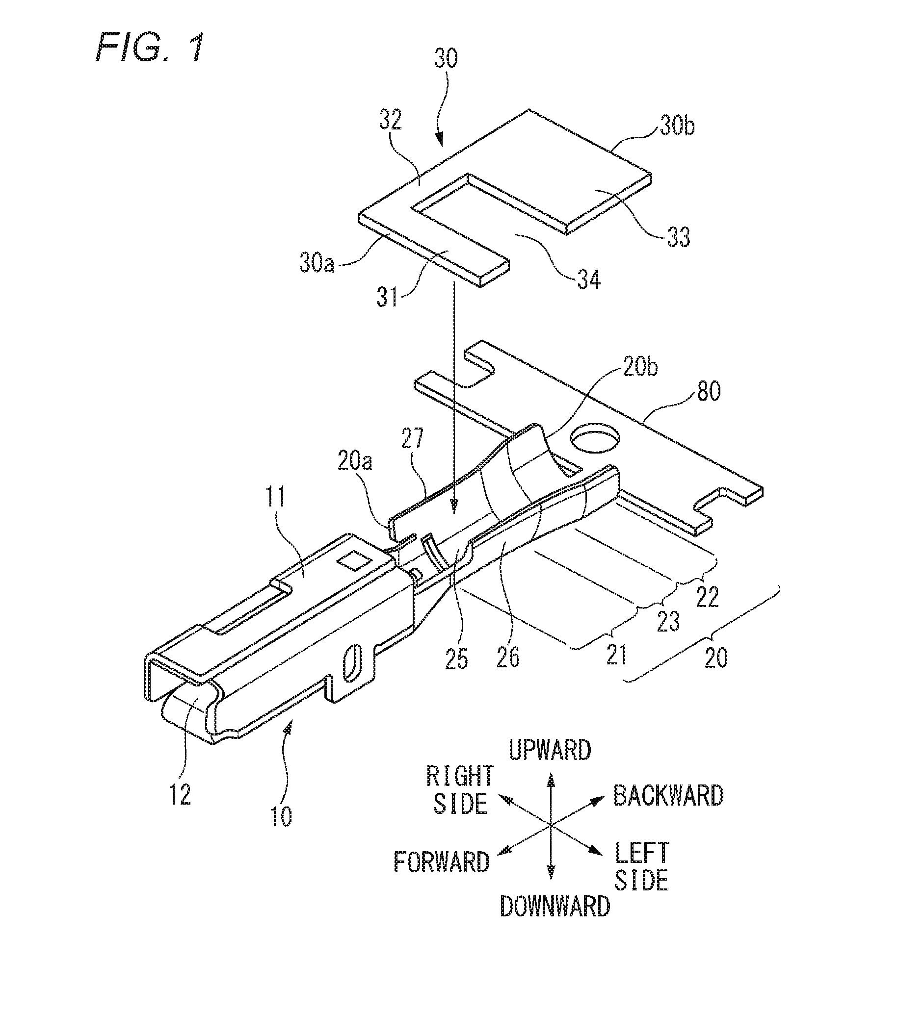
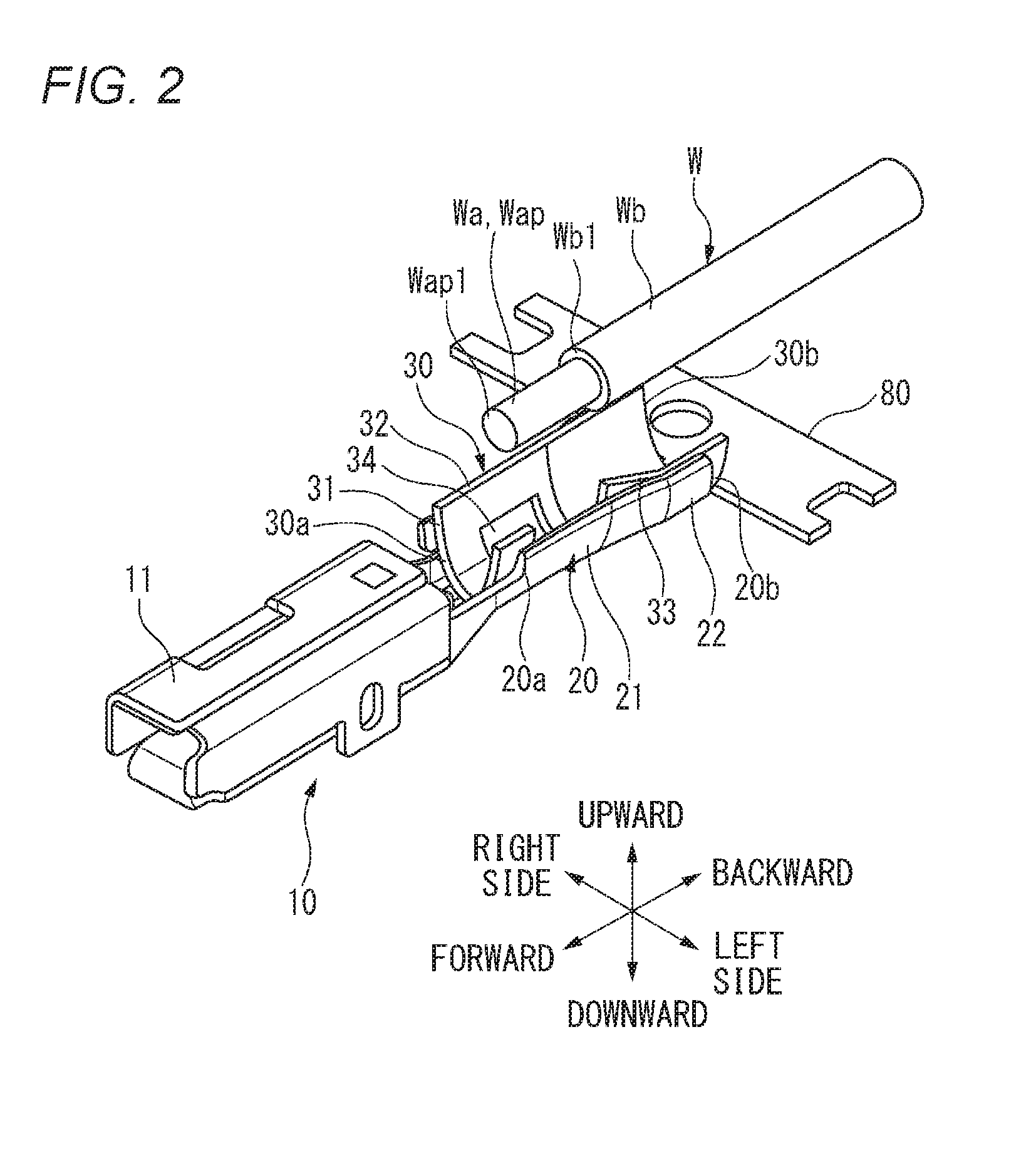
[0089]FIG. 1 is an explanatory view describing a connection structure of a crimp terminal with respect to a wire of a first embodiment of the invention and a perspective view illustrating an aspect in which a waterproof sheet is disposed in a wire connection section of the crimp terminal. FIG. 2 is an explanatory view describing the connection structure of the crimp terminal with respect to the wire of the first embodiment of the invention and a perspective view illustrating an aspect in which an end portion of the wire is disposed in the wire connection section of the crimp terminal from above the waterproof sheet as the next process of FIG. 1. FIG. 3 is an explanatory view describing the connection structure of the crimp terminal with respect to the wire of the first embodiment of the invention and a perspective view illustrating a position where a conductor exposed section is disposed when disposing the end portion of the wire is in the wire connection section of the crimp termin...

second embodiment

[0115]Now, referring to the drawings, a second embodiment will be described below. FIG. 5 is an explanatory view describing a connection structure of a crimp terminal with respect to a wire of a second embodiment of the invention and is a perspective view illustrating an aspect in which an end portion of the wire is disposed in a wire connection section of the crimp terminal from above a waterproof sheet.

[0116]In the connection structure of a crimp terminal 10A with respect to a wire W of the second embodiment, since a waterproof sheet 30A is used instead of the waterproof sheet 30 according to the first embodiment described above, the same symbols are given to the other configuration members, and detailed description thereof will be omitted.

[0117]The waterproof sheet 30A according to the second embodiment is formed in a U shape similar to the waterproof sheet 30 according to the first embodiment.

[0118]The waterproof sheet 30A has a front sheet section 31A that is extended in a widt...

third embodiment

[0127]FIG. 6 is an explanatory view describing a connection structure of a crimp terminal with respect to a wire of a third embodiment of the invention and a perspective view illustrating an aspect in which a waterproof sheet is disposed in a wire connection section of the crimp terminal. FIGS. 7A to 7C are cross-sectional view describing a structure of the waterproof sheet illustrated in FIG. 6, in which FIG. 7A is a schematic cross-sectional view of the waterproof sheet. FIG. 7B is an enlarged cross-sectional view of a portion of FIG. 7A, and FIG. 7C is an enlarged cross-sectional view illustrating a state where a peeling sheet on a lower side in FIG. 7B is peeled. FIG. 8 is an explanatory view describing the connection structure of the crimp terminal with respect to the wire of the third embodiment of the invention and a plan view illustrating an aspect in which an end portion of the wire is disposed in the wire connection section of the crimp terminal from above the waterproof s...


PUM


Abstract

Herein disclosed is a connection structure including a waterproof sheet disposed in an inner surface of a wire connection section and has an opening section in a position corresponding to a conductor exposed section, in which the waterproof sheet is configured such that a front end of the waterproof sheet is positioned on a front side from a front end of a conductor crimp section and a rear end of the waterproof sheet is positioned on a rear side from a rear end of the cover crimp section.

Description

CROSS REFERENCE TO RELATED APPLICATIONS[0001]This application is a continuation of PCT application No. PCT / JP2014 / 072852, which was filed on Aug. 26, 2014 based on Japanese patent applications No. 2013-174769 filed on Aug. 26, 2013, No. 2013-174829 filed on Aug. 26, 2013, No. 2013-174830 filed on Aug. 26, 2013, No. 2014-057086 filed on Mar. 19, 2014, and No. 2014-077836 filed on Apr. 4, 2014, whose contents are incorporated herein by reference. Also, all the references cited herein are incorporated as a whole.BACKGROUND OF THE INVENTION[0002]1. Technical Field The present invention relates to a connection structure of a crimp terminal with respect to wire, with waterproof performance.[0003]2. Background Art[0004]Weight reduction of a vehicle significantly affects fuel economy improvement. At the present when reduction in carbon dioxide emissions is required, a wire made of a lightweight aluminum or an aluminum alloy is advantageously used in a wire harness, specifically in an electr...

Claims


Application Information

Patent Timeline
IPC IPC(8): H01R4/18H01R13/52
CPCH01R13/5205H01R4/185H01R4/62H01R13/52
Inventor AOKI, HIROSHIOHTAKA, KAZUTO
Owner YAZAKI CORP
Why Eureka
Try Eureka