Grounding link for electrical connector mechanism

Active Publication Date: 2016-05-19
THOMAS & BETTS INT INC
View PDF14 Cites 11 Cited by
  • Summary
  • Abstract
  • Description
  • Claims
  • Application Information

AI Technical Summary

Problems solved by technology

Unfortunately, 200 amp grounding elbows are only rated for a momentary fault current of 10 kiloamps, while 600 amp systems may require momentary fault currents of up to 25 kiloamps.

Method used


Image

  • Grounding link for electrical connector mechanism
  • Grounding link for electrical connector mechanism
  • Grounding link for electrical connector mechanism

Examples


Embodiment Construction

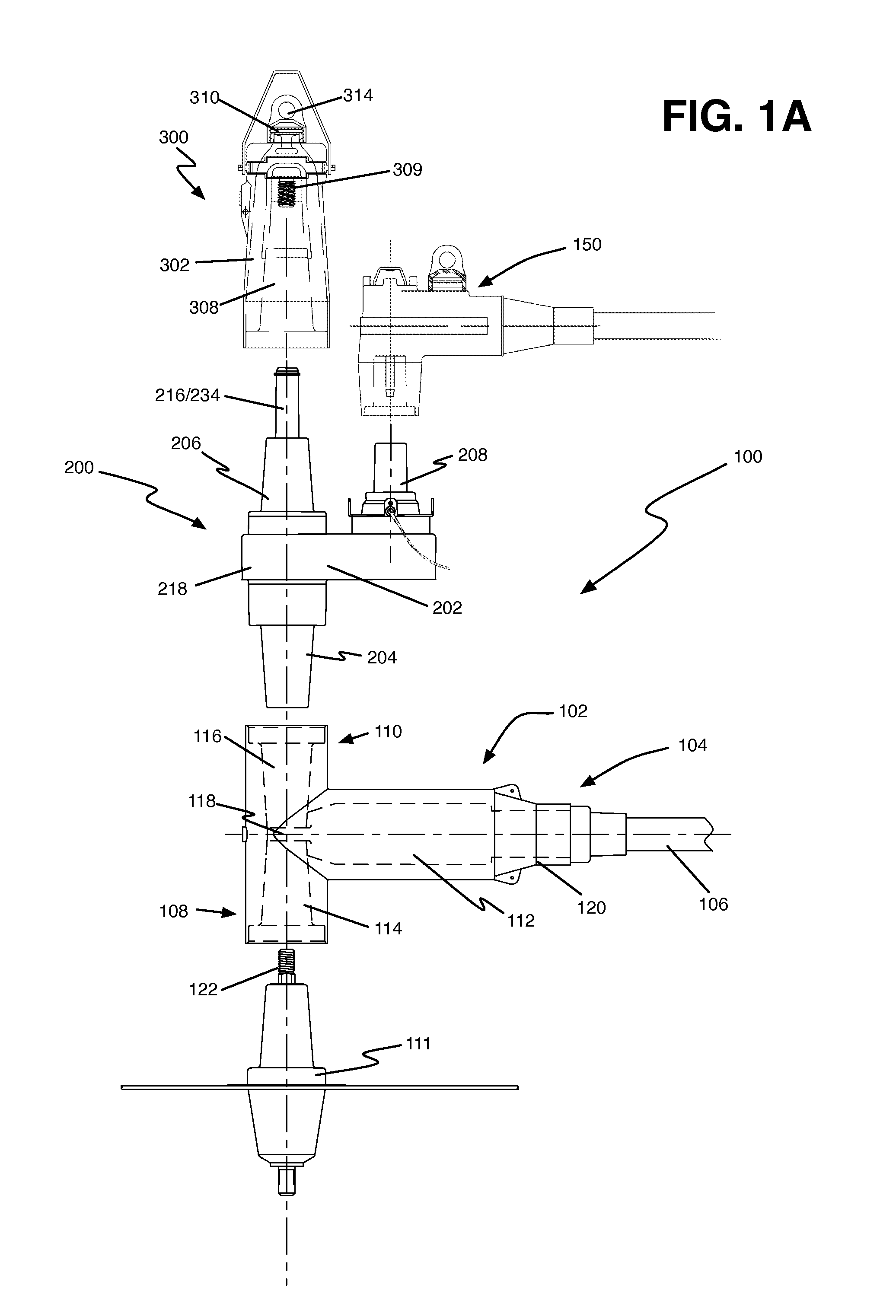
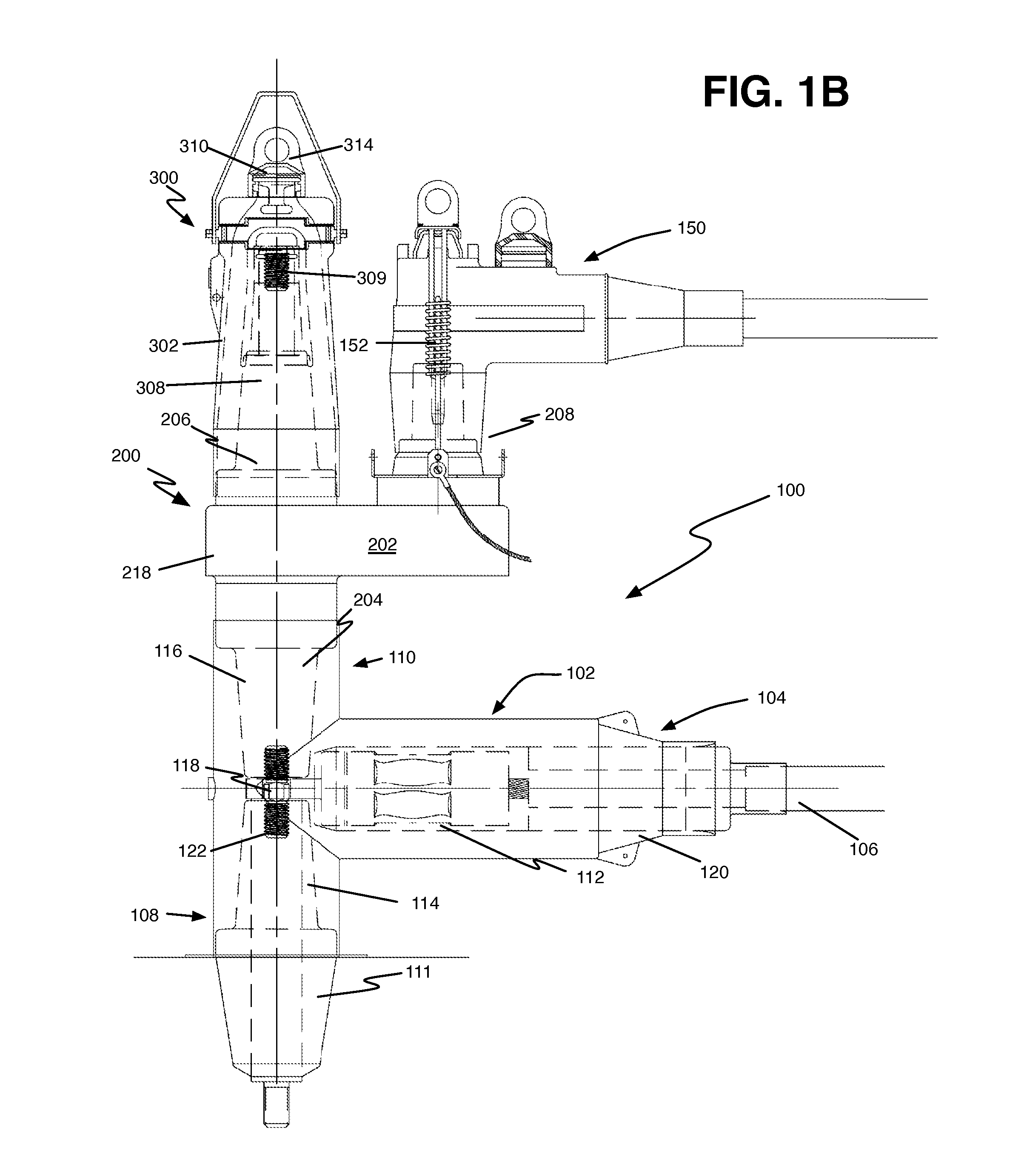
[0015]The following detailed description refers to the accompanying drawings. The same reference numbers in different drawings may identify the same or similar elements.

[0016]FIG. 1A is a schematic exploded side view of a power cable elbow connector assembly 100 consistent with implementations described herein, e.g., a 600 amp elbow assembly. FIG. 1B is a schematic side view of the power cable elbow connector assembly 100 in a first assembled configuration. FIG. 1C is a schematic side view of the power cable elbow connector assembly 100 in a second assembled configuration. As shown, power cable elbow connector assembly 100 may include a main housing body 102 that includes a conductor receiving end 104 for receiving a power cable 106 therein and first and second T-ends 108 / 110 that include openings for receiving an equipment bushing, such as a deadbreak or loadbreak transformer bushing 111 or other high or medium voltage. Consistent with implementations described herein, second T-end...


PUM


Abstract

A grounding link for use with an elbow-type power cable electrical connector. The grounding link includes a bushing interface portion, a cap receiving portion, and a tap portion, wherein the grounding link further includes a grounding element extending between the bushing interface portion and a cap receiving portion, and wherein the bushing interface portion of the grounding link is configured for insertion into a bore in elbow-type power cable electrical connector. The grounding element includes an exposed portion projecting above a surface of the grounding link, wherein the exposed portion of the grounding element is configured for attachment by a grounded hot line clamp to ground the electrical connector assembly. The tap portion is configured for receipt of a second elbow connector to conductively couple the second elbow connector to the elbow-type power cable electrical connector.

Description

CROSS-REFERENCE TO RELATED APPLICATION[0001]This application claims priority under 35. U.S.C. §119, based on U.S. Provisional Patent Application No. 62 / 080,496 filed Nov. 17, 2014, the disclosure of which is hereby incorporated by reference herein.BACKGROUND OF THE INVENTION[0002]The present invention relates to electrical cable connectors, such as loadbreak connectors and deadbreak connectors. More particularly, aspects described herein relate to an electrical cable connector, such as a power cable elbow or T-connector connected to electrical switchgear assembly.[0003]Loadbreak and deadbreak connectors used in conjunction with 15 through 35 KV switchgear generally include power cable elbow connectors having one end adapted for receiving a power cable and another end adapted for receiving a loadbreak / deadbreak bushing insert or other switchgear device. The end adapted for receiving the bushing insert generally includes an elbow cuff for providing an interference fit with a molded fl...

Claims


Application Information

Patent Timeline
Patent Type & Authority Applications(United States)
IPC IPC(8): H01R13/648H01R43/16
CPCH01R43/16H01R13/648H01R4/56H01R11/15H01R13/207H01R13/447H01R13/53H01R13/6599H01R31/02H01R2101/00
Inventor SIEBENS, LARRY N.BORGSTROM, ALAN D.
Owner THOMAS & BETTS INT INC
Why Eureka
Try Eureka